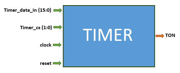
8.4 The Timer.
The timer operates two modes: Up counter and down counter. This is controlled by the
timer_cs signal. The
timer_cs signal is a two-bit signal which turns on the timer unit and also selects whether a up conter or down counter. If the up count is selected, then the counter register counts from zero to the value in the
timer_datain. If a down count is selected, then the counter register counts down from the value in the
timer_datain down to one.
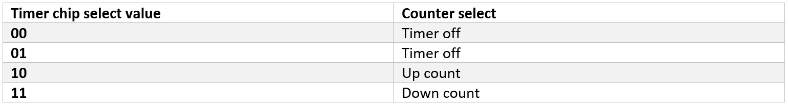
The table above shows how the timer chip select bits are implemented. The timer turns on only when bit1 is high or when the
timer_cs is greater than two. Then if the bit0 is equal to zero or low, then an up count is selected while if it is high then a down count is selected.
The timer has four internal registers: The counter register, the timer_data_in register, the up_count register and the down_count register.
The timer_data_in register stores the value in the
timer_data_in signal. During the Up counter mode,
the counter register counts from zero to the value in the timer_data_in register.
The up_count register is set to one throughout this period and the
TON signal is ON, indicating a count is taking place. When the counter register equals the timer_data_in register the up_count register resets.
During the Down counter mode, the counter register counts from the value in the timer_data_in register down to zero.
The down_count register is set to one throughout this period and the
TON signal is ON, indicating a count is taking place.
When the counter register equals to one or zero the down_count register resets.
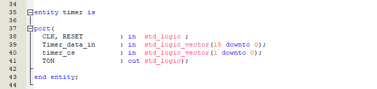
8.5 The Timer.vhd
First, we would introduce the title.
Next the IEEE; standard library.
The ports listed above, is introduced.
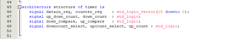
The signals below, will be used in the circuit. They would be introduced down in the circuit.
We would use two types of counter. The up counter and the down counter. To use the up counter , the
counter_reg (counter register) counts from zero to the value in the
datain_reg (data_in register). At this point, the
up_compare signal comes on. To use the down counter , the
counter_reg (counter register) counts from the value in the
datain_reg (data_in register) down to one. At this point, the
down_compare signal comes on. When the up counter is selected the
upcount_select is turned ‘on’ and if the down counter is selected the
downcount_select is turned on. The
up_count signal is used to make sure that the up count is selected when the
up_compare signal is turned ‘on’, while the
down_count signal is used to make sure that the down count is selected when the
down_compare signal is turned ‘on’. The
up_down_count signal checks if either the
up_count or
down_count.
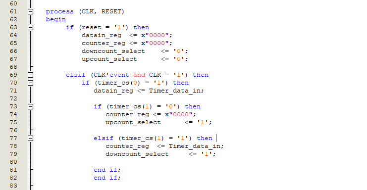
For every clock cycle, the
timer_cs (timer chip select) is a 2-bit signal used to control the timer unit. Bit1 is used to turn on the timer unit, when this bit is high the
datain_reg loads the data in the
timer_data_in. This data is used for the up count and down count. If bit0 of
timer_cs is low, then the up count is selected. At this point, the
upcount_select is set to ‘1’ and the
counter_reg is set to zero to be able to count upwards. If bit0 of
timer_cs is high, then the down count is selected. At this point, the
downcount_select is set to ‘1’ and the
counter_reg is set to the value in the
timer_data_in, from this value it counts down.
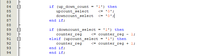
When the up count or down count is complete that is, when the counter register counts up to
datain_reg or when the counter register counts down from the
datain_reg down to one. The
up_down_count is turned on and tat this point the
upcount_select and the
downcount_select are reset to zero. If the
downcount_select is high,then the counter register is decrementing while if the
upcount_select is high then the counter register is incrementing.
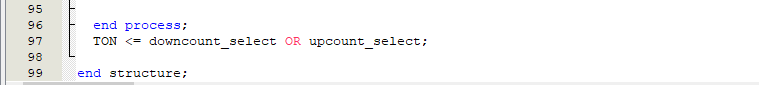
The main output signal of the timer unit is the
TON. This is ‘on’ when the counter register is counting for the up count or for the down count.
8.6 The Timer.h
The
timer_datain register is in the register unit, and this register holds the timer data. So, let us include
register.h.
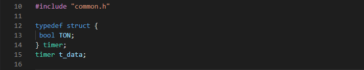
Next, let us create the timer struct called
timer t_data. This struct will consist of only the timer ouput called
TON, this signal is only high when the timer unit is counting.
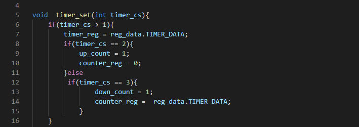
The timer unit has only one function which is used to set the timer. This function is called
timer_set and it takes only one argument which is the timer chip select.
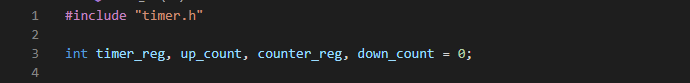
8.7 The Timer.c
We start by including the 'timer.h'. Then we introduce some variables or signals which i would explain later.
if the
timer_cs is greater than one, that is when it is either ‘10’ or ‘11’ in binary or when bit1 is equal to '1' in binary then the timer unit comes on. At this point, the
timer_reg (timer register) takes the value of the
TIMER_DATA in the register struct called
reg_data.
if bit0 of the timer_cs is low, that is when the timer chipselect is ‘10’. Then the up counter is selected and the up_count signal is set to ‘1’. The counter register is also set to zero. Consequently, if bit0 of the timer_cs is high, that is when the timer chipselect is ‘11’. Then the down counter is selected and the down_count signal is set to ‘1’. The counter register is also set to the value in the timer register.
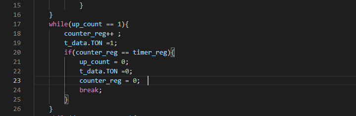
During an up count. The
up_count signal is high. While this signal is high, the counter register starts incrementing, and the
TON is set high until the counter register equals the value in the timer register. At this point, the
up_count signal is set to zero, the counter register and the
TON signal are both set to zero.
During a down count. The
down_count signal is high. While this signal is high, the counter register starts decrementing from the value in the timer register towards one, and the
TON is set high until the counter register equals the value ‘1’. At this point, the
down_count signal is set to zero, the counter register and the
TON signal are both set to zero.