7.1 Why do we need a Stack?
A stack is a linear data structure, elements are stacked on top of each other. Only the last element added can be accessed, i.e the element at the top of the stack. That is, a stack is a Last In First Out (LIFO) structure. This is the opposite of a queue which is First in First out (FIFO). Both hardware and software stacks have been used to support four major computing areas in computing requirements: expression evaluation, subroutine return address storage, dynamically allocated local variable storage, and subroutine parameter passing. BrainIO will incorporate the stac and use it for backtracking, return address storage and solving complex maths operation. This will be explained more in walkalong2 building the software.
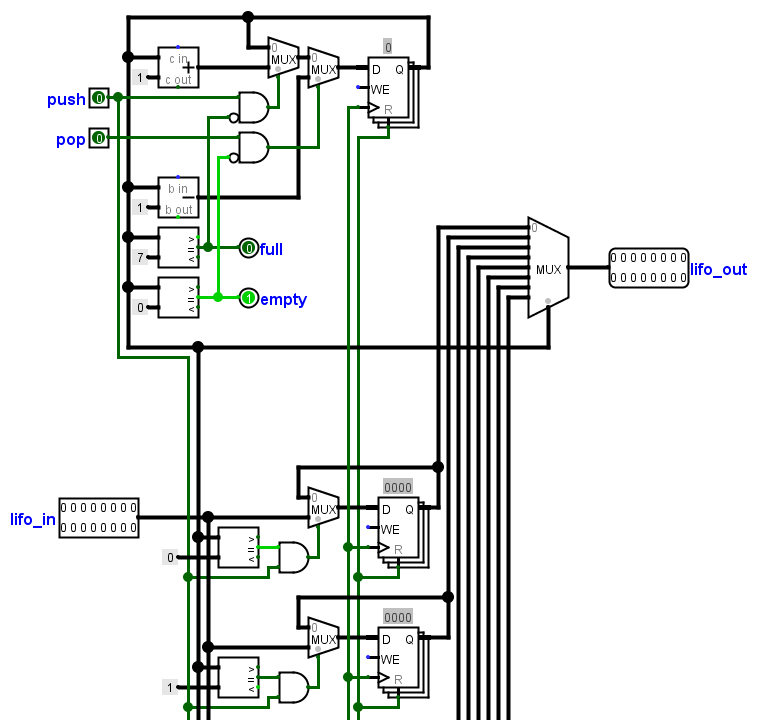
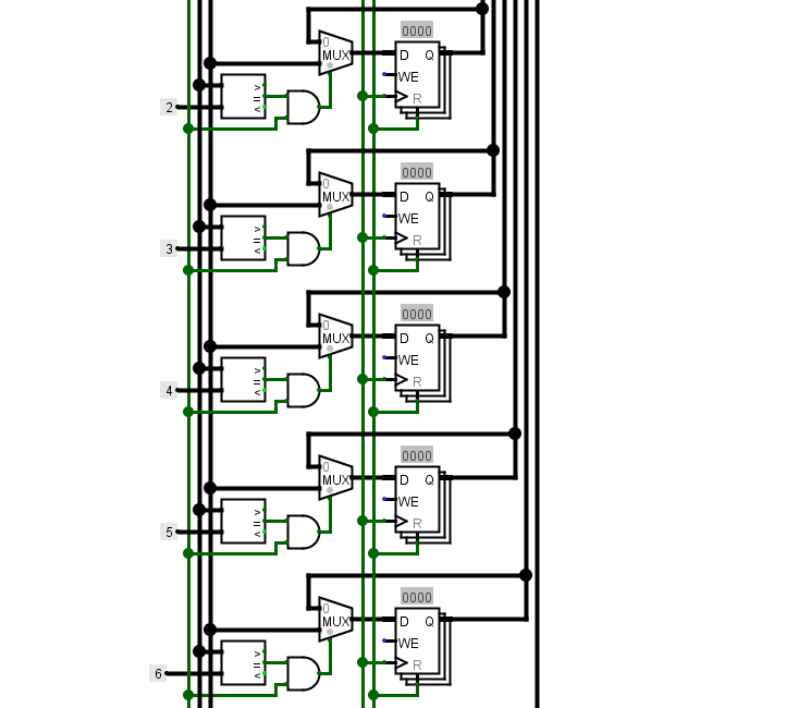
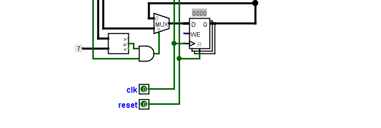
7.2 The Schematic
At the top right corner of the schematic is the address register.The address register is a pointer to the address of the register where the push or pop operation is to be performed. Two multiplexers to this register are controlled by the push and pop signal which either increment or decrement the address register by one using an adder and subtractor connected to them. Two 'AND' gates are used to make sure the LIFO is not empty during a pop operation and it is not full during a push operation. The LIFO_OUT which is the ouptut of the LIFO is connected directly to the output of the registers through a multiplexer controlled by the address register during a pop operation. The inputs of the eight 16-bit data registers are also controlled by the address register which compares its data with the address of each register using a comparator. The 'AND' gate makes sure that a pop signal is high before the LIFO_IN is stored in the register.
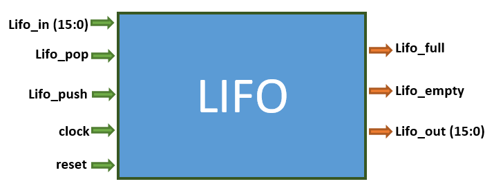
7.3 The PINOUTS
The LIFO also known as Stack is mainly used for storing temporary data, for storing local variables and for storing return addresses after interrupts.
The Lifo_in register stores the next data to be pushed on to the stack, and if the push signal comes on the Lifo_in
data is pushed on to the stack. The Lifo_out always points to the top of the Stack, and when the pop signal comes on , the top data on the
Lifo_out is popped out and the stack goes to the next item. The push and pop signal works by incrementing and decrementing the Stack pointer register
within the stack sub unit. The address or data stored in this register determines where to push the Lifo_in data or where to pop the Lifo_out data.
This stack consists of a total of eight 16-bit registers to store data, this implies that the stack pointer increments or decrements from 0 – 7 depending on whether
it is a push or pop operation. The stack pointer is a single 3-bit register that counts from binary 000 to binary 111. The empty and full
indicates the state of LIFO and can be read directly by the program. They also prevent a Pop operation when the LIFO is empty and prevents a Push operation when the LIFO is full.
The LIFO or stack is very similar to FIFO which we will discuss next.
7.4 Difference between a LIFO and FIFO
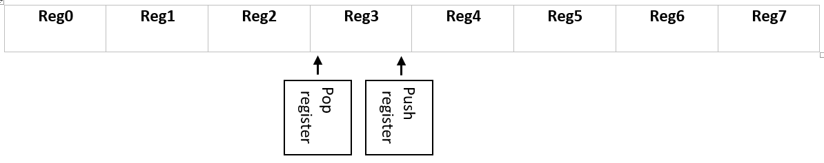
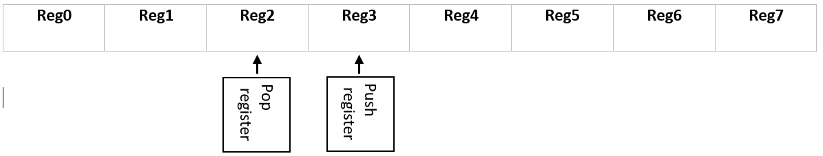
The FIFO has two address register called the pop register and push register. Initially when both registers are on address 0. The FIFO is empty.
The push register is always ahead of the pop register. Its function is to write data while the pop register reads.
Whenever both registers are equal, the FIFO is empty and no further pop operation is allowed.
Whenever the registers counts upto ‘111’, they return to zero and start counting again. Therefore, the push register only lags behind the pop register when it has counted to ‘111’ and returned and at this point it is still leading.
When the push register is one step behind the pop register, that is when it is going to take one step before it meets the pop register again the FIFO is assumed to be full and no further push operation is allowed at this point.
The condition below is different from the one above, when the pop register is one step behind the push register , it is still allowed to pop until they are both equal and the FIFO is empty again.
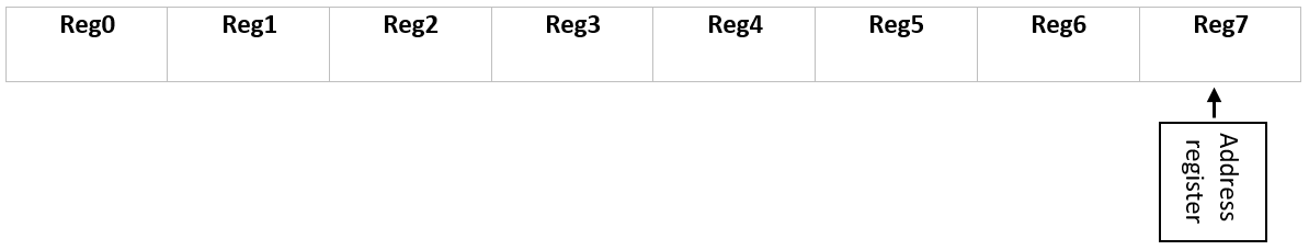
The LIFO only has one address register for both push and pop operation. The LIFO is empty only when it is at zero.
The LIFO is only full when it is at ‘111’
7.5 LIFO.vhd
First, we declare the title.
Next we declare the IEEE; standard library
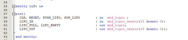
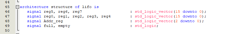
Now let us declare the entity named ‘Lifo’ consisting of the pinouts we learnt above.
The signals would consist of the eight 16-bit registers, the 3-bit address register called Addr_reg and finally the full and empty signal.
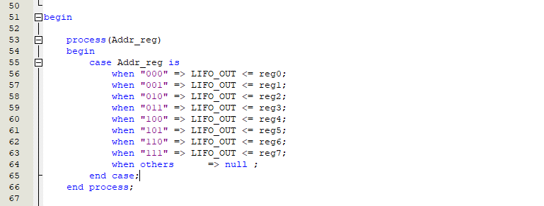
The Addr_reg determines which register to pop into the LIFO_OUT output. So, we would create a case for it.
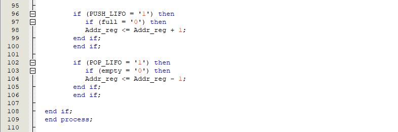
The Addr_reg also determines which register to push the LIFO_IN data during a push operation. The LIFO_IN push data is behind a clock while the LIFO_OUT popped data is directly connected to the outputs.
The full signal is used to determine if the lifo is full. This signal only allows a push operation when low. The empty signal also determines if the LIFO is empty and it only allows a pop operation when low.
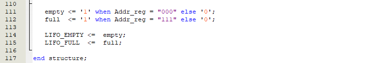
The empty signal turns on when the LIFO is empty, that is when the Addr_reg is equal to "000". The full signal turns on when the LIFO is full, that is when the Addr_reg is equal to "111".
Finally, the empty and full signal is assigned to the LIFO_EMPTY and LIFO_FULL.
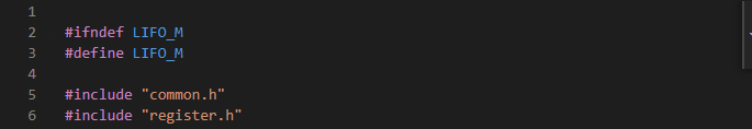
7.6 LIFO.h
The lifo register is in the register unit, and it is this register that contains the lifo data input. We include the ‘register.h’ to access this data.
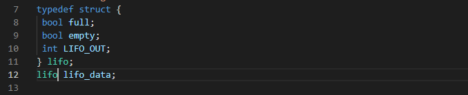
Next, we create the lifo struct called lifo lifo_data. It would contain the lifo output and the full and empty signal.
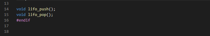
Then, we would declare its two operations. Push and pop.
7.7 LIFO.c
We would start by including ‘lifo.h’ . Then we initialize the address register and the lifo registers. The lifo registers is an array of eight items representing the registers.
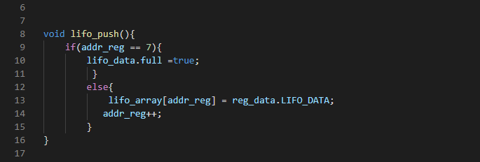
Lets declare the push(). We would first of all check if the lifo is full. If it is full we would set the full signal in the lifo struct to true and exit. If it is not full, then we proceed to write the content of the LIFO_DATA which is in the register data struct called reg_data to the lifo array using the addr_reg as the address. Finally, we increment the address to point to the next register.
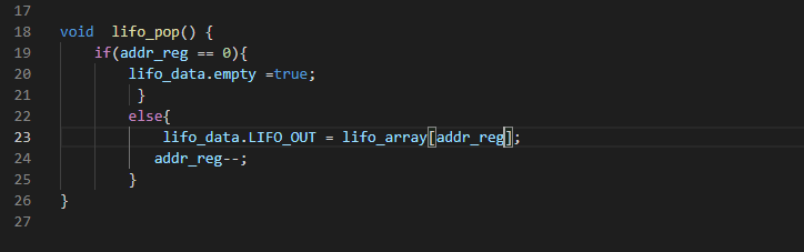
Lets declare the pop(). We would first of all check if the lifo is empty. If it is empty, we would set the empty signal in the lifo struct to true and exit. If it is not empty, then we proceed to write the content of the lifo array using the addr_reg as the selector to the LIFO_OUT which is in the LIFO struct called lifo_data. Finally, we decrement the address to point to the previous register.