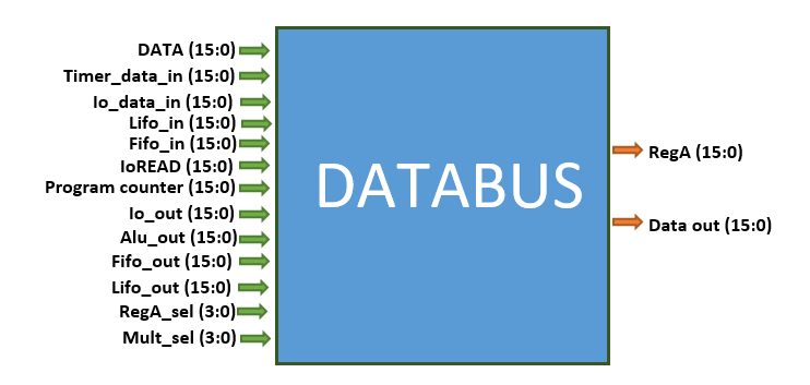
9.2 The Pinouts.
This unit has two major outputs that goes to different parts of the sub unit; they are the
regA and the
mult_out. Each of them have a particular selector which selects which of the inputs to use as outputs: for the
regA the selector is
regA_sel
while for the
mult_out the selector is
mult_sel. These inputs includes both input and outputs from different units. The table below shows where each input is generated from and what select bits are required to select them.
| Select Data |
Source |
select bit |
| data | Output from the program memory | 0000 |
| timer_data_in | input to timer unit | 0001 |
| io_data_in | input to I/O unit (write pin) | 0010 |
| lifo_in | input to LIFO unit | 0011 |
| fifo_in | input to FIFO unit | 0100 |
| ioREAD | input to I/O unit (read pin) | 0101 |
| program_couter | Input to the Program memory | 0110 |
| io_out | Data output from I/O unit | 0111 |
| alu_out | Output from the ALU register | 1000 |
| fifo_out | Output from the FIFO unit | 1001 |
| lifo_out | Output from the LIFO unit | 1010 |
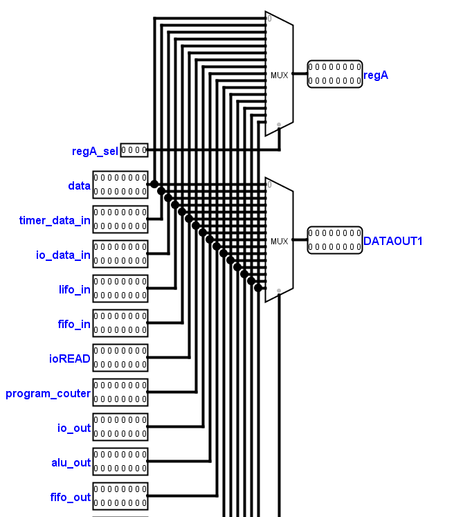
9.3 The schematic.
The schematic below shows two seperate multiplexers for the two different outputs of the databus. As can be seen, both multiplexers share thesame inputs which are positioned at thesame positions. What this means, is that if both multiplexer share thesame select bit, they produce thesame output. The inputs are the same as shown above. The unlabelled inputs will be tied to zero since they are connected anywhere. In later version of brainio we might make use of them. The instruction can produce different values for their select bits thereby giving different outputs.
9.4 databus.vhd
Let us introduce the title.

Include the IEEE; standard library

The ports are given in the diagram above
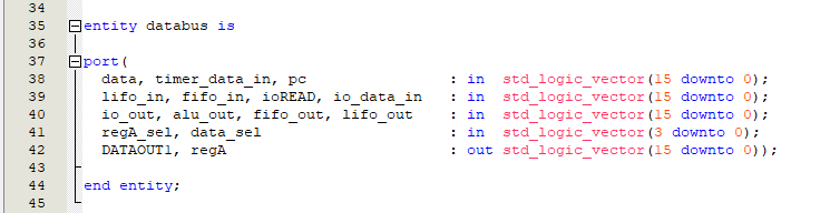
The databus has two main output or multiplexer output. One is the
DATAOUT1. The
data_sel signal is used to select the
DATAOUT1 output. The databus receives its input from all the sub units and using its data selector which comes from the instruction, decides which of them to set as output and which sub unit to send it.

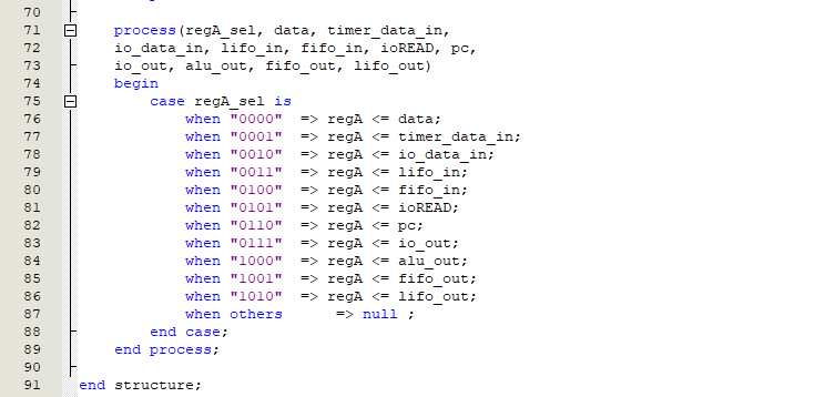
The next output is the
regA. The
regA_sel signal is used to select the
regA output. Both the
DATAOUT1 and the
regA share the same set of inputs but their data selectors are different.
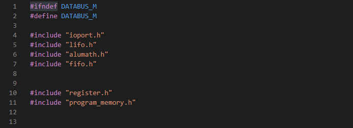
9.5 databus.h
The databus consist of two 4-bit select multiplexer which receives input from all the sub units and gives two outputs. Since it receives input from all the subunit we would include all the sub unit header files.
The databus gives two outputs called:
regA and
MULT_OUT. We would use an enum called
output_select to select the particular output we need.

We would another enum called
databusOp which would consist of all the inputs to the databus:
TIMER_DATA_IN, IO_DATA_IN, LIFO_IN, FIFO_IN, IOREAD, PROGRAM_COUNTER, INTERRUPTS are all registers in the register unit.
IO_OUT, FIFO_OUT, LIFO_OUT, ALU_OUT are all outputs from different subunits.
DATA is from the instructions.

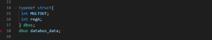
Next we define the databus struct called
dbus databus data which consists of the two databus output namely;
MULTOUT and
regA.
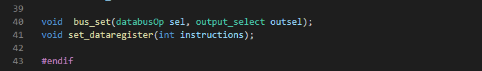
The databus unit has two main functions: the
bus_set and
set_dataregister. The
bus_set is used to select the output of this unit and consists of two arguments. The
databusOp sel which is used to select the particular input and the
output_select outsell which is used to select which output to use , whether it is
regA or
MULT_OUT. Two types of instructions are available in brainio. The executable instruction and data. When the decode unit decodes an instruction and finds out that it is not an executable instruction but a data, it will set this function which takes the data instruction as its argument. This function will then set the data register or
DATA (also one of the inputs of the databus) to the value of the instruction.
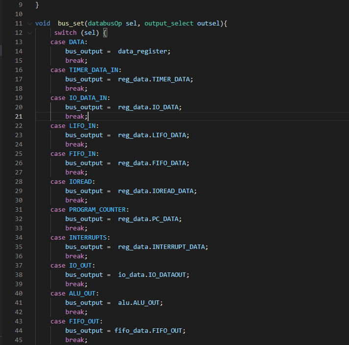
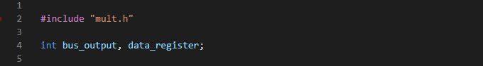
9.6 databus.c
We start by including the databus header file. Then two variables: the
bus_output this will store the output of the databus.
data_register, which will store the data instruction.
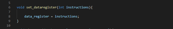
The
set_dataregister, will set the
data_register as the value of the instruction.
The
bus_set switches the
sel and depending on the value will set the
bus_output as one of the inputs.
After setting the
bus_output, depending on the value of the
outsel , one of the outputs of the databus will be set to the
bus_output.