In this section we would describe the pinout of the basy-3 board.
 Basy-3 pin out
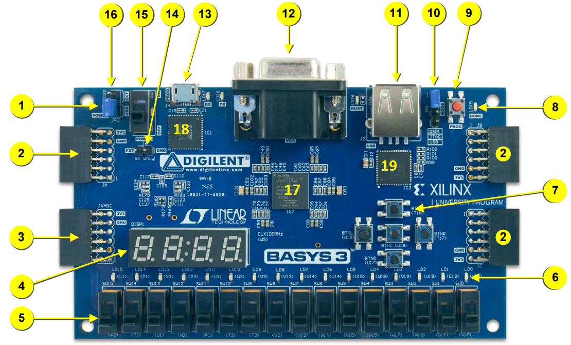
| 1Power good LED: indicates that the supplies are turned on and operating normally |
| 2Pmod port(s): Used for digital input/output |
| 3Analog signal Pmod port (XADC): They are connected to the FPGA analog input pins and Used by the XADC for digital signal processing. |
| 4Four digit 7-segment display: They are connected in common anode form and used for output display. |
| 5Slide switches (16): These switches can be used as input to the FPGA. Depending on the state of a switch, it can either generate constant input of logic level zero or one to the FPGA. |
| 6LEDs (16): They are used as output from the FPGA. When a logic level one is applied to an LED, it turns on. When a logic level zero is applied to an LED, it turns off. |
| 7Pushbuttons (5): These can be used as input to the FPGA. |
| 8FPGA programming done LED: This Led turns on, when the FPGA is successfully configured. |
| 9FPGA configuration reset button: This button can be used to reset the FPGA configuration. |
| 10Programming mode jumper: can be used to set the FPGA programming method. |
| 11USB host connector: The FPGA needs to be configured to operate. [11], [13] or [18] is used to feed this configuration file to the FPGA. [11] also have USB human interface device (HID) capability with the help of the PIC24FJ128 microcontroller[19] connected to this connector. |
| 12VGA connector:This connector allows 12-bit data transfer (four bits for red, four bits for blue, four bits for green pins) to a VGA display device. |
| 13Shared UART/ JTAG USB port:The FPGA needs to be configured to operate. [13] is used to feed this configuration file to the FPGA another method is using [18]. To do so, the configuration file should have been stored in flash beforehand.[13] Can also be used to power the basy3 board and , it can also be used as a UART medium to communicate the FPGA with the help of the USB-UART Bridge. |
| 14External power connector: External power supply is connected here to power up the board with DC voltage between 4.5 and 5.5 V with at least 1-A current |
| 15Power Switch: Used to turn the board On/Off. |
| 16Power Select Jumper: Used to select power source to the board between [13] and [14]. |
| 17FPGA chip: This is the main Artix-7 FPGA chip. This gives the board its name. |
| 18USB-UART bridge:Used as an alternative method to load configuration files to the FPGA it involves using the SPI flash. To do so, the configuration file should have been stored in flash beforehand. |
| 19 auxiliary function microcontroller: Is a PIC24FJ128 microcontroller, used in conjunction with [11], to feed configuration file to the FPGA. |
Other features includes