In this tutorial , we will describe the Arty board pinouts.
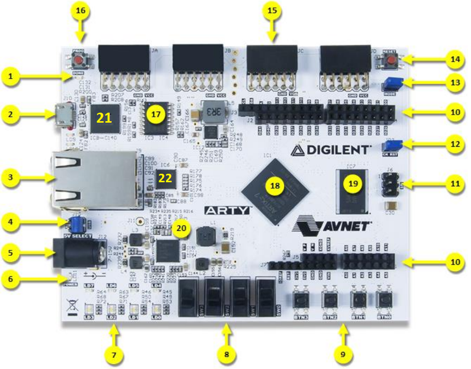 Arty hardware callout descriptions
| 1FPGA programming DONE LED:This led turns on When the FPGA is successfully configured. |
| 2Shared USB JTAG/UART port:It is mainly used to configure (program) the FPGA it also has a USB-UART bridge connected to it this enables it to be used as a UART medium to communicate the FPGA with PC or another device it is also used to power the board. |
| 3 Ethernet connector:It is used with [22] to enable ethernet communication . |
| 4Power select jumper (Ext. supply/USB): can be used to select the power source to be fed to the board. |
| 6Power good LED : It indicates that the board is turned on and operating normally. |
| 7User LEDs: They consist of four tricolor LEDs (labeled as LD0–LD3 on the board) and four standard LEDs (labeled as LD4–LD7 on the board). |
| 8User slide switches: They serve as inputs to the FPGA board. |
| 9User push-buttons : They serve as inputs to the FPGA board. |
| 10Arduino/chipKIT shield connectors :They allow user to connect available Arduino and chipKIT shields and Can be used to power the board. |
| 11SPI header (Arduino/chipKIT compatible):It is an Arduino/chipKIT compatible SPI header used in connection with Arduino/chipKIT compatible shields. |
| 12 and 14 chipKIT processor reset jumper and chipKIT processor reset : they can be used to reset soft-core microcontroller designs. |
| 13FPGA programming mode (JTAG/Flash): can be used to set the FPGA programming method. |
| 15Pmod headers:They are used for digital input/output. |
| 16FPGA programming reset button:can be used to reset the FPGA configuration. |
| 17SPI Flash:It serves as an external memory blocks , it is a 128-Mbit non-volatile serial flash memory and connected to the Artix-7 FPGA through a dedicated SPI bus. |
| 18Artix FPGA: Artix-7 FPGA, the main FPGA chip. |
| 19Micron DDR3 memory: It is a 256-MB DDR3L SDRAM. |
| 20Analog devices ADP 5052 power supply: Used to regulate input voltage to the board. |
| 21USB-UART Bridge: It is used together with UART/JTAG USB as a UART medium to communicate the FPGA with PC or another device. |
| 22 Transceiver chip:It is also called physical layer(PHY).It is used with [3] to enable ethernet communication . |
Other features includes