This is the last chapter of this tutorial, At this point we have built the baud generator subcircuit, transmitter subcircuit and receiver subcircuit.
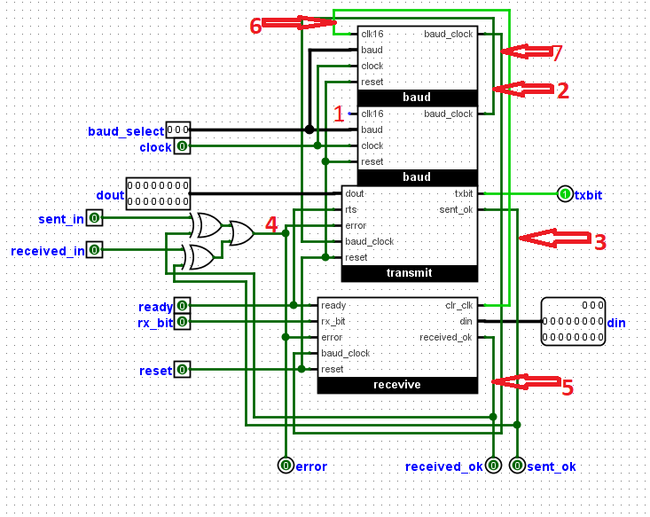
We will now connect them together as shown in the diagram below using VHDL.
For geeks who do not use logisim should note that ports with round or circular shapes are output ports while square-headed ports are input.
The circuit has been tested on quartus on modelsim and works perfectly fine.
You would notice that the receiver and transmitter share
a different baud generator instead of one, this is because of the oversampling at the receiver, The receiver resets the baud The_counter
immediately it receives a '0' or a start bit and this could interrupt the transmitter , so a seperate clock generator is made for them.
A seperate appication will be developed at the end of the project to demonstrate how they work


--------------------------------------------------------------------------------
-- PROJECTFPGA.COM
--------------------------------------------------------------------------------
-- NAME:    UART TRANSCEIVER
--------------------------------------------------------------------------------
-- AUTHORS: Ezeuko Emmanuel <ezeuko.arinze@projectfpga.com>
--------------------------------------------------------------------------------
-- WEBSITE: https://projectfpga.com/uart
--------------------------------------------------------------------------------
--------------------------------------------------------------------------------
-- UART TRANSCEIVER FOR FPGA
--------------------------------------------------------------------------------
-- Copyright (C) 2020 projectfpga.com
--
-- This source file is free software: you can redistribute it and/or modify
-- it under the terms of the GNU Lesser General Public License as published by
-- the Free Software Foundation, either version 3 of the License, or
-- (at your option) any later version.
--
-- This source file is distributed in the hope that it will be useful,
-- but WITHOUT ANY WARRANTY; without even the implied warranty of
-- MERCHANTABILITY or FITNESS FOR A PARTICULAR PURPOSE.  See the
-- GNU Lesser General Public License for more details.
--
-- You should have received a copy of the GNU Lesser General Public License
-- along with this program.  If not, see <http://www.gnu.org/licenses/>.
--------------------------------------------------------------------------------


library ieee;
use ieee.std_logic_1164.all;

entity transceiver is
  port(
    reset, ready, rx_bit, received_in, sent_in, clock: in std_logic;
	 baud_select : in std_logic_vector(2 downto 0);
	 dout : in std_logic_vector(15 downto 0);
    error, received_ok, sent_ok, txbit : out std_logic;
	 din : out std_logic_vector(18 downto 0)
  );
end transceiver;

architecture structure of transceiver is

  component baud_generator
port(
  baud_select : in  std_logic_vector(2 downto 0);
  clr_clk, reset, clock : in  std_logic;
   baud_clock : out std_logic);
    end component;

	  component transmitter
port(
  dout : in  std_logic_vector(15 downto 0); --data to be transmitted
  rts : in  std_logic;--set by receiver to tell transmitter to start sending data
  baud_clock : in  std_logic;--The baud clock, will be used instead of main clock
  reset , error: in  std_logic;
  txbit: out std_logic;
  sent_ok: out std_logic);
    end component;


	  component receiver
port(
   received_ok: out std_logic;
  rx_bit : in  std_logic;--The received bit
  baud_clock : in  std_logic;--The baud clock, will be used instead of main clock
  reset : in  std_logic;
  error, ready: in std_logic;
  clr_clk: out std_logic;--resets the baud_clock to zero
    din : out  std_logic_vector(18 downto 0));
    end component;


  signal s_clr_rx, tx_baud_clock, s_sent_ok, s_error, s_received_ok: std_logic;
  signal s_clr_clk, rx_baud_clock: std_logic;

begin

s_error <= (sent_in xor s_received_ok)  or (received_in xor s_sent_ok) ;

  eq_bit0: baud_generator
    port map (baud_select, s_clr_rx, reset, clock, tx_baud_clock);


  eq_bit1: baud_generator
    port map (baud_select, s_clr_clk, reset, clock, rx_baud_clock);


  eq_bit2: transmitter
    port map (dout=>dout, rts=>ready,
	 baud_clock=>tx_baud_clock, reset=>reset, error=>s_error,
	 txbit=>txbit, sent_ok=>s_sent_ok);

	   eq_bit3: receiver
    port map (rx_bit=>rx_bit, baud_clock=>rx_baud_clock, error=> s_error, ready => ready,
	 reset=>reset, received_ok=>s_received_ok, clr_clk=>s_clr_clk, din=>din);

end structure;
