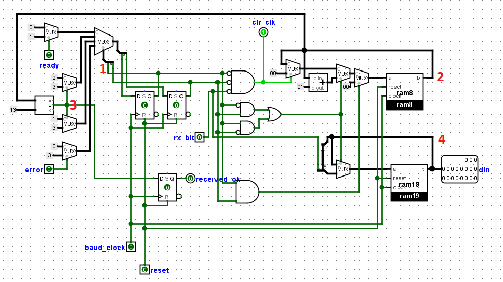
As can be seen from the left side of the diagram below, the receiver state machine consists of four states, it has two outputs A and B, which will be fed into the state action subcircuit. The circuit is clocked with the baud clock generated earlier, the clock16 input is the oversampling input. The RX bit is the received bit, the receiver line is always kept high when idle. This is why the start bit is usually a zero, this wakes up the receiver as shown in the diagram. The rxbitcnt input keeps record of number of received bits. It starts counting after receiving the start bit which is zero, and stops when it reaches 'nobits' input which keeps record of the number of bits that is supposed to be received.


Oversampling occurs here, since there is no common clock, to synchronize the reception of data, the receiver will set the clock_16 counter to 8. The clock_16 counter which normally counts to 16 will be set to 8, so that by the time it gets to 16, the baud_clock rising edge will occur at the middle of the start bit. and this is the oversampling. This subcircuit consists of 3 Rams as can be from the right side of the image above, Ram8 keeps record of number of bits received immediately after the start bit. Ram19 stores the received bits. Then the shift register which shifts the bit in once they have been received. Data_in output is the received bits. and the two rx_bits are the same they will joined together using VHDL, rxbit is the received bit.
--------------------------------------------------------------------------------
-- PROJECTFPGA.COM
--------------------------------------------------------------------------------
-- NAME:    UART RECEIVER
--------------------------------------------------------------------------------
-- AUTHORS: Ezeuko Emmanuel <ezeuko.arinze@projectfpga.com>
--------------------------------------------------------------------------------
-- WEBSITE: https://projectfpga.com/uart
--------------------------------------------------------------------------------
--------------------------------------------------------------------------------
-- UART RECEIVER FOR FPGA
--------------------------------------------------------------------------------
-- Copyright (C) 2020 projectfpga.com
--
-- This source file is free software: you can redistribute it and/or modify
-- it under the terms of the GNU Lesser General Public License as published by
-- the Free Software Foundation, either version 3 of the License, or
-- (at your option) any later version.
--
-- This source file is distributed in the hope that it will be useful,
-- but WITHOUT ANY WARRANTY; without even the implied warranty of
-- MERCHANTABILITY or FITNESS FOR A PARTICULAR PURPOSE.  See the
-- GNU Lesser General Public License for more details.
--
-- You should have received a copy of the GNU Lesser General Public License
-- along with this program.  If not, see <http://www.gnu.org/licenses/>.
--------------------------------------------------------------------------------


library IEEE;
use IEEE.std_logic_1164.all;
use IEEE.numeric_std.all;
use IEEE.STD_LOGIC_ARITH.ALL;
use IEEE.STD_LOGIC_UNSIGNED.ALL;
entity receiver is
port(
   received_ok: out std_logic;
  rx_bit : in  std_logic;--The received bit
  baud_clock : in  std_logic;--The baud clock, will be used instead of main clock
  reset : in  std_logic;
  error, ready: in std_logic;
  clr_clk: out std_logic;--resets the baud_clock to zero
    din : out  std_logic_vector(18 downto 0)); --received data
end entity;
architecture structure of receiver is
signal RXFSM : std_logic_vector(1 downto 0);--stores the current state
signal rxbitcnt : std_logic_vector(7 downto 0);
signal nobits : std_logic;
signal data_reg : std_logic_vector(18 downto 0);

begin
 din       <= data_reg;
nobits <= '1' when (rxbitcnt = "1101") else '0';
clr_clk <= not RXFSM(0) and not RXFSM(1) and   not rx_bit;


process (reset, baud_clock)
begin
if reset='1' then
 RXFSM <=  (others => '0');
  rxbitcnt <=  (others => '0');
   received_ok <=  '0';
	 data_reg <=  (others => '0');
  elsif rising_edge(baud_clock) then
  received_ok <= nobits;


   case RXFSM is

  when "00" =>
  if rx_bit ='0' then
  rxbitcnt <= (others => '0');
  end if;
  if ready = '1' then
  RXFSM <="01";
  else
 RXFSM <= "00";
  end if;

  when "01" =>
  data_reg <= rx_bit & data_reg(data_reg'high downto 1);
  rxbitcnt <= rxbitcnt + 1;
  if nobits = '1' then
  RXFSM <="11";
 else
  RXFSM <="10";
  end if;

  when "10" =>
  data_reg <= rx_bit & data_reg(data_reg'high downto 1);
  rxbitcnt <= rxbitcnt + 1;
  if nobits = '1' then
  RXFSM <="11";
 else
  RXFSM <="01";
  end if;

when "11" =>
  rxbitcnt <= (others => '0');
  if error = '1' then
	RXFSM <= "11";
else
	RXFSM <= "00";
end if;

	end case;
end if;
end process;
end structure;