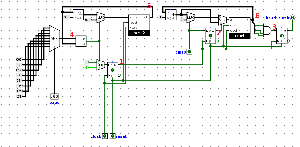
UART is an asynchronous transmission scheme and so the correct clock rate must be defined prior to transmission to ensure that the data
is transmitted and received correctly. Transmission and reception of data are not being clocked or controlled by the same source(clock).
Therefore the transmitter and receiver must be able to send and receive data at the same rate by generating from their original clock source a common
clocking frequency, else if data is being sent and received at different clocking speed ,some will be lost during transmission. This common clocking speed is called the BAUDRATE.It is same as the number of bits per
second (bps) and is common among receiver and transmitter and has to be set before data is sent or received. An oversampling scheme is commonly used to locate the middle position of the transmitted bits, i.e., where the actual sample is taken. some standard baud rates includes
300, 1200, 2400, 4800, 9600,
19.2K, 38.4k, 57.6k, 115.2k…
In this unit we would design the baud generator. This circuit will generate the baud
or clocking speed from the original system clock.The most common oversampling rate is 16 times the baud rate.
Therefore, each serial bit is sampled 16 times but only one sample is saved as
we will see. In an Example asumming standard clock frequency of 14.7456 MHz and baud of say, 19200.
                         We first Oversample it 16 times
                       (14.7456 * 1,000,000) / 16 = 921,600.
                               921,600 / 19200 = 48
                        =47 since counting starts from zero.
          This means to get a baud of 19200, from a standard clock of 14.7456MHz
            the system clock needs a counter to tick after every 47 counts, and
             then oversampled 16 times . Other baudrates can also be generated
                                   using this method.


--------------------------------------------------------------------------------
-- PROJECTFPGA.COM
--------------------------------------------------------------------------------
-- NAME:    UART BAUD GENERATOR
--------------------------------------------------------------------------------
-- AUTHORS: Ezeuko Emmanuel <ezeuko.arinze@projectfpga.com>
--------------------------------------------------------------------------------
-- WEBSITE: https://projectfpga.com/uart
--------------------------------------------------------------------------------
--------------------------------------------------------------------------------
-- UART BAUD GENERATOR FOR FPGA
--------------------------------------------------------------------------------
-- Copyright (C) 2020 projectfpga.com
--
-- This source file is free software: you can redistribute it and/or modify
-- it under the terms of the GNU Lesser General Public License as published by
-- the Free Software Foundation, either version 3 of the License, or
-- (at your option) any later version.
--
-- This source file is distributed in the hope that it will be useful,
-- but WITHOUT ANY WARRANTY; without even the implied warranty of
-- MERCHANTABILITY or FITNESS FOR A PARTICULAR PURPOSE.  See the
-- GNU Lesser General Public License for more details.
--
-- You should have received a copy of the GNU Lesser General Public License
-- along with this program.  If not, see <http://www.gnu.org/licenses/>.
--------------------------------------------------------------------------------


library IEEE;
use IEEE.std_logic_1164.all;
use IEEE.numeric_std.all;
use IEEE.STD_LOGIC_ARITH.ALL;
use IEEE.STD_LOGIC_UNSIGNED.ALL;
entity baud_generator is
port(
  baud_select : in  std_logic_vector(2 downto 0);
  clr_clk, reset, clock : in  std_logic;
   baud_clock : out std_logic);
end entity;
architecture rtl of baud_generator is
signal clock_16                 : std_logic;
signal clr_clkreg               : std_logic;
signal baud_clockreg            : std_logic;
signal clk_counter              : std_logic_vector(11 downto 0);
signal accumulator              : std_logic_vector(11 downto 0) ;
signal clock_16_counter         : std_logic_vector(3 downto 0) ;


begin
baud_clockreg <= '1' when (clock_16_counter = "1111") else '0';

baud_selector: process (baud_select)
begin
 case baud_select is       --        baud rates
 when "000"                       => clk_counter <= X"007"; --  115.200
 when "001"                       => clk_counter <= X"00F"; -- 57.600
 when "010"                       => clk_counter <= X"017"; -- 38.400
 when "011"                       => clk_counter <= X"02F"; -- 19.200
 when "100"                       => clk_counter <= X"05F"; -- 9.600
 when "101"                       => clk_counter <= X"0BF"; --4.800
 when "110"                       => clk_counter <= X"17F"; --2.400
 when "111"                       => clk_counter <= X"2FF"; --1.200
 when others                      => clk_counter <= X"007"; -- 115.200
 end case;
 end process baud_selector;


 The_counter: process (reset, clock)
 begin

if reset='1' then
 accumulator <=  ( others => '0');
 clock_16 <= '0';
 elsif rising_edge(clock) then
 if clk_counter = accumulator then
 accumulator <= ( others => '0');
 clock_16 <= '1';
 else
accumulator <= accumulator + 1;
  clock_16 <= '0';
 end if;
 end if;
end process  The_counter;


 The_oversampling_stage: process (reset, clock_16)
begin
 if reset='1' then
  baud_clock <= '0';
  clr_clkreg <= '0';
  clock_16_counter <=  ( others => '0');
  elsif rising_edge(clock_16) then
  baud_clock   <= baud_clockreg;
  clr_clkreg    <= clr_clk;
  if (clr_clk = '0') then
  clock_16_counter<= clock_16_counter + 1 ;
  elsif(clr_clk = '1' ) then
  if ( clr_clkreg = '0') then
  clock_16_counter<= "1000";
  end if;
  end if;

end if;
end process The_oversampling_stage;


end rtl;
Leave a comment below if you have issues understanding the code.