In this tutorial we will be implementing the TCP/IP protocol suite
using verilog/VHDL to be implemented on an actual FPGA board, we will discuss The various terms associated with the protocol
including CSMA/CD, Error detection and checking techniques, CRC etc. This tutorial is long and complex so I would also include
part of my youtube videos for demonstration purposes.Full verilog code and logism circuits will be provided all through the course.
The tutorial is intended for people with knowledge of Logism and Verilog or VHDL coding with interest in serial communication protocols.
1.0 What is a Protocol ?
A protocol is a set of rules that govern how systems communicate. For networking they govern how data is transferred from one system to another.
Protocol Stacks
It is possible to write a single protocol that takes data from one computer application and sends it to an application on another computer.-
A Single stack Protocol
The problem with this approach is that it very inflexible, as any changes require changing the entire application and protocol software.
The approach used in networking is to create layered protocol stacks.
Each level of the stack performs a particular function and communicates with the levels above and below it.
What is a Protocol Suite ?
A protocol suite is a collection of protocols that are designed to work together.
The TCP/IP protocol suite is a collection of protocols that are used on the Internet. It is commonly known as TCP/IP because
the foundational protocols in the suite are the Transmission Control Protocol (TCP)
and the Internet Protocol (IP) and specifies how data should be packetized, addressed, transmitted, routed and received.
This functionality is organized into four abstraction layers, which classify all related protocols according to the scope of networking involved.
From lowest to highest, the layers are the
→ link layer the Link Layer, provides mechanisms for indicating which device the communications are to and from on the circuit, which device is allowed to transmit next, controlling the flow of information to deal with limited capacities, and detecting bit errors.
→ the internet layer, provides internetworking between independent networks;
→ the transport layer, its main role of the transport layer is to provide the communication services directly to the application processes running on different hosts. Two major protocols at this layer are the TCP and UDP (User Datagram Protocol).
→ the application layer, provides process-to-process data exchange for application. It is the closest layer to the end user which means that the application layer and end user can interact directly with the software application. The IEEE specifies Ethernet addressing in standard 802.2, as part of the Media Access Control (MAC) sublayer, so these addresses are often called MAC addresses .

1.2 Types of Ethernet addresses
The MAC address comprises of a 48-bit number.
Within the number the first 24 bits identify the manufacturer and it is known as the manufacturer ID or Organizational Unique Identifier (OUI)
and this is assigned by the registration authority. The second half of the address is assigned by the manufacturer
and it is known as the extension of board ID.
There are three types of MAC address; unicast, multicast, and broadcast.
Unicast MAC address → A unicast MAC address is the unique address uses for sending a packet from a single transmitting device to a single destination device.
Multicast MAC address → represents a group of devices in a LAN. A frame sent to a multicast address will be forwarded to a group of devices on the LAN. Multicast frames have a value of 1 in the least-significant bit of the first octet of the destination address. This helps a network switch to distinguish between unicast and multicast addresses. One example of an Ethernet multicast address would be 01:00:0C:CC:CC:CC, which is the address used by CDP (Cisco Discovery Protocol). The online games also use multicast addresses, where many players connected remotely but playing the same game. Another use of the multicast address is in distance learning through video conferencing, where many students connected to the same class.
Broadcast MAC address → Frames sent to a broadcast address will be delivered to all devices on the LAN. The broadcast address has the value of FFFF.FFFF.FFFF (all binary ones). The switch will flood broadcast frames out all ports except the port that it was received on.

1.3 The Ethernet Frames.
The Ethernet frame is defined in the Data link layer. A typical ethernet frame is given above,
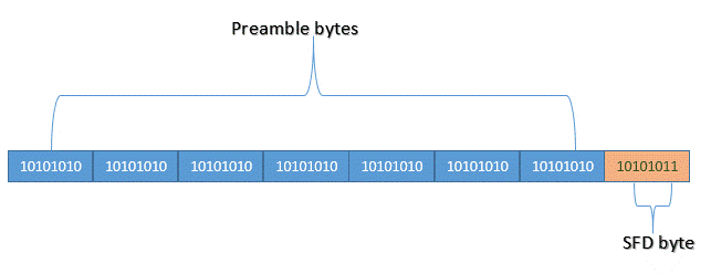
The basic frame consists of seven elements split between three main areas; an Ethernet header (Preamble, SFD, Destination, Source, and Type),
Encapsulated data (Data and Pad), and an Ethernet trailer (FCS).


Note: According to section 3.3 of the IEEE 802.3 standard, each octet of the Ethernet frame, with the exception of the FCS, is transmitted low-order bit first.
The total size of the ethernet frame must be between 64 bytes and 1,518 bytes (not including the preamble). A frame shorter than the minimum 64 bytes but with a valid CRC is called as a runt. In most cases, such frames arise from a collision or a damaged network card. Any frame which is received and which is greater than the maximum frame size, is called a "giant". A "giant" is longer than 1518 bytes yet have a valid CRC. Both runts and giants are considered as invalid ethernet frames.
1.5 Ethernet Data Transmission Modes
CSMA/CD stands for Carrier Sense Multiple Access with Collision Detection. For example, one node-A wants to transmit the data to node-B connected on Ethernet medium. The software running on node-A sends the data to NIC (Network Interface Card) to build the packet. The packet is stored in the RAM of NIC and node-A monitors the bus. If no carrier is present on the Ethernet network, node-A transmits the packet over the medium. The data is broadcasted to all the PCs connected on the Ethernet bus. All the receiving nodes compare destination Ethernet address and whoever nodes' Ethernet address matches it will accept the packet from the medium and rest of the others will discard the packet. Whenever any one of the nodes transmits the information on the bus, all the PCs detect what is known as carrier. Carrier is nothing but the data transmitted over the bus at some rate as specified by Ethernet standard. If collision is detected when two or more nodes try to transmit at the same time then nodes will wait for some random period of time and will transmit again. This protocol is referred as CSMA/CD. The CSMA/CD protocol used for Ethernet and a variety of other applications falls into three categories. The first is Carrier Sense. Here each station listens on the network for traffic and it can detect when the network is quiet. The second is the Multiple Access aspect where the stations are able to determine for themselves whether they should transmit. The final element is the Collision Detect element. Even though stations may find the network free, it is still possible that two stations will start to transmit at virtually the same time. If this happens then the two sets of data being transmitted will collide. If this occurs then the stations can detect this and they will stop transmitting. They then back off a random amount of time before attempting a retransmission. The random delay is important as it prevents the two stations starting to transmit together a second time.
1.7 How is Data Communicated from one Machine to Another ?To communicate data from one machine to another on the circuit, the transmitting station's Ethernet software takes a block of data and puts the Media Access Control sublayer (MAC) address of the desired destination device on the front of the block, along with the source MAC address, control information, framing and the FCS at the end of the block, creating the frame. Next, the transmitting machine checks if any other machines are using the circuit. If so, the transmitting station must wait. When the circuit is free, the transmitting station signals the MAC frame one bit at a time by flashing a light on and off on Optical Ethernet, by changing the voltage up and down on a copper LAN cable, or transmitting a modem signal using a radio on a wireless connection. All devices on the circuit receive the frame, verify if there are errors, then compare the destination MAC address from the frame to the MAC address on their LAN interface. If they are the same, then the device knows it should react to the frame. The result is to move a block of data from one machine to another machine on the same physical circuit. This is the purpose of Ethernet, MAC addresses and frames.