SPI
1.0 What is SPI
SPI stands for Serial Peripherial Interface.It is a synchronous serial communication
interface specification used for short-distance communication in digital systems. . SPI is used between
two or more digital components where one is called the master and the rest are slaves.
They communicate in full duplex(they receive and transmit data at the same time) mode
using a master-slave architecture with a single master. The master solely controls the
sending and reception of data. Multiple slave-devices are also supported through selection
with individual ports called the slave select (SS) or sometimes called chip select (CS), lines.
Its typical applications include peripheral communications like
- Sensors: temperature, pressure, ADC, touchscreens, video game controllers.
- Control devices: audio codecs, digital potentiometers, DAC.
- Camera lenses: Canon EF lens mount.
- Communications: Ethernet, USB, USART, CAN, IEEE 802.15.4, IEEE 802.11, handheld video games.
- Memory: flash and EEPROM.
- Real-time clocks.
- LCD, sometimes even for managing image data.
- Any MMC or SD card (including SDIO variant.
1.1 SPI callouts
Sometimes SPI is called a four-wire serial bus, A simple SPI configuration
consisting of a single master and a single slave is shown above, from the diagram we can see the pinout of the master and slave.
- 1. SCLK → It is called Serial Clock (output from master).
This is the master clock that controls all other slaves and it is provided by the master for all the slaves.
- 2. MOSI → This stands for Master Out Slave In (data output from master). This pin
is used by the master to send data to the slaves. MOSI on a master connects to MOSI on a slave.
It can also be referred to as SIMO(Slave in Master out) or MTSR (Master Transmit Slave Receive) on both
the master and the slave. On the Slave alone it can be called SDI (Slave Data in) or DI or DIN(Data in) or
SI(Slave in).
- 3. MISO → This stands for Master In Slave Out (data output from slave). This pin is used
by the Master to receive from the slaves, if they are more than one slave the SS Pin is used to determine which slave the master
wants to talk to.It is also referred to as SOMI(Slave out Master in) or MRST (Master receive Slave Transmit)
on both the master and the slave. On only the slave it is referred to as SDO(Slave Data out) or DO or DOUT
(Data out) or SO (Slave out). On the Master only it is called SDI (Slave Data in) or DI or DIN
(Data in) or SI(Slave in).
- 4. Slave Select → This pin is used by the Master to select which slave to talk to.
It is usually an active low pin(A slave is selected when 0 is sent to it). It is also called CE(Chip Enable) or CSN
(Chip Select/ Enable) or CS(Chip Select).
.
1.2 Multiple Slaves Configuration
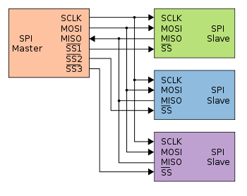
The SPI bus can operate with a single master device and with one or more slave devices as can be seen from the diagram above.
If a single slave device is used, the SS pin may be fixed to logic low if the slave permits it. With multiple slave devices,
an independent SS signal is required from the master for each slave device .
The MOSI , MISO and SCLK are common to all the Slaves as it is only the SS that determines which Slave the Master is communicating
to at a particular time. If multiple slaves are used they will sually have tri-state outputs so their MISO signal becomes high impedance
(electrically disconnected) when the device is not selected. Devices without tri-state outputs cannot share SPI bus segments with other devices
without using an external tri-state buffer. We will show this when we would be writing the VHDL code.
1.3 Daisy-chain Configuration
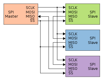
Some products that implement SPI may be connected in a daisy chain configuration shown above, In this configuration the MOSI and MISO lines are not
common to the slaves. To send data to any of the slaves the SS is turned low then data is sent from the MOSI of the master and loops
through all the slaves till it gets to the slave which is selected. Same way is Master wants to receive data from any Slave.
The SS pin of the slave is selected and the Slave sends its data through its MISO line and loops
through the other slaves till it gets to the Master i.e the first slave output being connected to the second slave input, etc.
The SPI port of each slave is designed to send out during the second group of clock pulses an exact copy of the data
it received during the first group of clock pulses. The whole chain acts as a communication shift register; daisy
chaining is often done with shift registers to provide a bank of inputs or outputs through SPI. Each slave copies
input to output in the next clock cycle until active low SS line goes high. Such a feature only requires a single
SS line from the master, rather than a separate SS line for each slave.


