FIR Filter
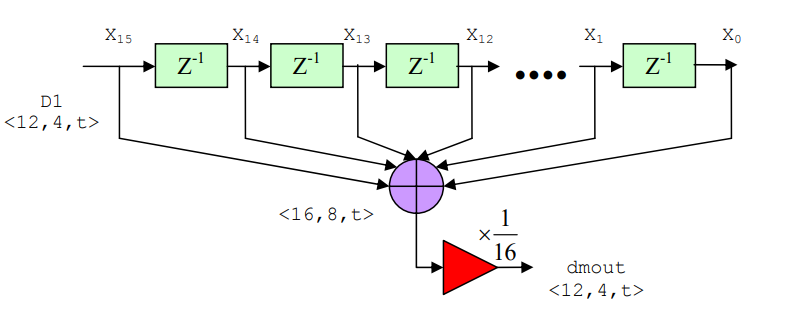
The last stage of the receiver system is to perform signal shaping. Here we use 16 tap Finite Impulse Response (FIR) filter to perform digital low pass filter.
This filter is essentially average filter since its output is equal to the average value of its input over the last n-tap samples, where n is number of tap used [4].
This configuration needs 16 coefficients, but simplification is taken by assuming all of the coefficients are the same, 1/16. In reality 1/16 multiply can be implemented by just
4 bit right shift operation. Then no multiplier is required.

LIBRARY ieee;
USE IEEE.std_logic_1164.all;
USE IEEE.numeric_std.ALL;


entity FIR is
port(
	clock		: in std_logic;
	reset		: in std_logic;
	data_in	: in signed(11 downto 0);
	data_out	: out std_logic_vector(11 downto 0)
);
end FIR;

architecture behavior of FIR is

signal d0,d1,d2,d3,d4,d5,d6,d7,d8,d9,d10,d11,d12,d13,d14,d15 : signed(15 downto 0);
signal sum	: signed(15 downto 0);

begin

process(clock,reset)
begin
	if (reset = '1') then
	d0 <= (others => '0');
	d1 <= (others => '0');
		d2 <= (others => '0');
		d3 <= (others => '0');
		d4 <= (others => '0');
		d5 <= (others => '0');
		d6 <= (others => '0');
		d7 <= (others => '0');
		d8 <= (others => '0');
		d9 <= (others => '0');
		d10 <= (others => '0');
		d11 <= (others => '0');
		d12 <= (others => '0');
		d13 <= (others => '0');
		d14 <= (others => '0');
		d15 <= (others => '0');
		sum <= (others => '0');
		data_out <= (others => '0');
	ELSIF rising_edge(clock) THEN
		d0 <= data_in(11)&data_in(11)&data_in(11)&data_in(11)&data_in;
		d1 <= d0;
		d2 <= d1;
   	d3 <= d2;
		d4 <= d3;
		d5 <= d4;
		d6 <= d5;
		d7 <= d6;
		d8 <= d7;
		d9 <= d8;
		d10 <= d9;
		d11 <= d10;
		d12 <= d11;
		d13 <= d12;
		d14 <= d13;
		d15 <= d14;
		sum <= (d0+d1+d2+d3+d4+d5+d6+d7+d8+d9+d10+d11+d12+d13+d14+d15) srl 4;
		data_out <= std_logic_vector(sum(11 downto 0));
	end if;
end process;
end behavior;