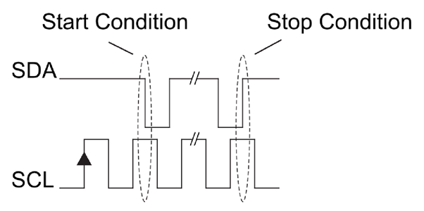
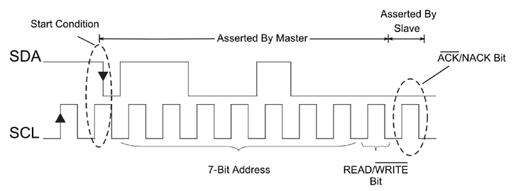
The data signal is transferred in sequences of 8 bits. So after a special start condition occurs comes the first 8 bits sequence which indicates the address of the slave to which the data is being sent. After each 8 bits sequence follows a bit called Acknowledge. After the first Acknowledge bit in most cases comes another addressing sequence but this time for the internal registers of the slave device. Right after the addressing sequences follows the data sequences as many until the data is completely sent and it ends with a special stop condition.

Start Condition: start condition always occurs at the start of a transmission and is initiated by the MASTER device. This is done to wake the idling SLAVE devices on the bus. This is one of the two times the SDA line is allowed to change state when SCL is high. To signify a start condition, the SDA line transitions from HIGH state to LOW state, while SCL is HIGH.
Stop Condition: the stop condition occurs at the end of a data transfer, and is also generated by the MASTER.
This signifies the end of the transfer and is a command to tell the slave devices that they should go back to an idle state,
release the SDA line and not send any more data on the bus. This is the second instance where the SDA line is allowed to change
state when SCL is HIGH. The SDA line transitions from LOW to HIGH state, while SCL is HIGH, to signify a stop condition.
In all other conditions the SDA line only changes state when the SCL line is LOW.

Read/Write Bit: A single bit specifying whether the master is sending data to the slave (low voltage level) or requesting data from it (high voltage level).
Address Frame : I2C doesn’t have slave select lines like SPI, so it needs another way to let the slave know that data is being sent to it, and not another slave. It does this by addressing. The address frame is always the first frame after the start bit in a new message. The device addressing sequence starts with the most significant bit (MSB) first and ends with the least significant bit (LSB) and it’s actually composed of 7 bits because the 8th bit is used for indicating whether the master will write to the slave (logic low) or read from it (logic high). The master sends the address of the slave it wants to communicate with to every slave connected to it. Each slave then compares the address sent from the master to its own address. If the address matches, it sends a low voltage ACK bit back to the master. If the address doesn’t match, the slave does nothing and the SDA line remains high.
Acknowledge and Not Acknowledge Bits (ACK/NACK)
As a form of feedback, after every byte transmission the receiving device sends an Acknowledge or Not Acknowledge bit.
An Acknowledge bit is generated by the receiver by holding the SDA line low during a HIGH SCL period, while a
Not Acknowledge bit is generated when the receiver leaves the SDA line passively pulled HIGH and does not respond in any way.
This fact implies that in response to an address byte, all unmatched SLAVEs send a Not Acknowledge bit by not responding.
An ACK is used to denote that a byte (address or data) was transmitted and received successfully and that the transmission
can continue on to the next byte transfer, a stop condition or a repeated start (Figure 4). A NACK is generally used by the
receiver to indicate whether an error occurred somewhere in the data transmission. This is used to signal to the transmitting
device to terminate the transmission immediately or to make another attempt by sending a repeated start.

The Data Frame After the master detects the ACK bit from the slave, the first data frame is ready to be sent. The data frame is always 8 bits long, and sent with the most significant bit first. Each data frame is immediately followed by an ACK/NACK bit to verify that the frame has been received successfully. The ACK bit must be received by either the master or the slave (depending on who is sending the data) before the next data frame can be sent. After all of the data frames have been sent, the master can send a stop condition to the slave to halt the transmission. The stop condition is a voltage transition from low to high on the SDA line after a low to high transition on the SCL line, with the SCL line remaining high.
Command Byte When writing to or reading from a specific register in a SLAVE, the master must first point to the specific register by writing the register address once the SLAVE has been addressed. While the register address can be considered a data byte, to avoid confusion it is often classified as a Command byte.
Steps involve for writing the data from Master to Slave: 1. To start communication, Master first sends a START command to the bus. 2. Then sends the 7-bit unique address of the desired slave with the write operation command set to 0. 3. Wait for the acknowledgement (ACK) from the slave/receiver. 4. All connected slaves listen to the address and matched slave responses with ACK byte set. 5. For successful acknowledgement, it sends the required internal 8-bit register address of the slave to which data needs to be written. 6. The selected slave matches the register address, If matches, sends the ACK bit to set otherwise, it sends NACK byte (Non-Acknowledgement byte, describe later.) 7. Master again waits for the acknowledgement. 8. For successful acknowledgement, write the 8-bit data to the slave. When complete data is written on the slave, Slave sends an acknowledgement bit ACK to the Master to notify that it is the end of the writing process. 9. The Master then sends a STOP command as a termination signal to the bus. And this process goes on until Master writes the complete data to the slave.

