I2C communication is the short form for inter-integrated circuits.Also called TWI (Two wire interface) was developed by Philips Semiconductors for the transfer of data between a central processor and multiple ICs on the same circuit board using just two common wires. Owing to its simplicity, it is widely adopted for communication between microcontrollers and sensor arrays, displays, IoT devices, EEPROMs etc. It is a synchronous serial communication protocol. Meaning that data bits are transferred one by one at regular intervals of time set by a reference clock line.
It is also half-duplex bi-directional two-wire bus system for transmitting and receiving data between masters (M) and slaves (S). These two wires are named as Serial Clock Line (SCL) and Serial Data Line (SDA). The data to be transferred is sent through the SDA wire and is synchronized with the clock signal from SCL. We can then say that, SCL (serial clock line) is responsible for synchronizing the communication and is controlled by Master (the slave can also control the clock line, we will discuss about later) and SDA (serial data line) is responsible for providing the data bi-directionally and can be used by master or slave or both.
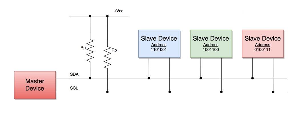
For differentiating between multiple slave devices connected to the same I2C bus, each slave device is physically assigned a permanent 7-bit address. When a master device wants to transfer data to or from a slave device, it specifies this particular slave device address on the SDA line and then proceeds with the transfer. So effectively communication takes place between the master device and a particular slave device. All the other slave devices doesn’t respond unless their address is specified by the master device on the SDA line. All the devices/ICs on the I2C network are connected to the same SCL and SDA lines as shown below:
1.1 Open-collector or open-drain bus
Both SCL and SDA lines are "open drain" drivers. What this means is that the chip can
drive its output low, but it cannot drive it high . In the figure below, we can see the internal structure of the I2C bus drivers SCL/SDA,
consisting of a buffer to read the input and a pull-down (short to GND) FET to transmit the data. A device is only able to pull the bus line
to go low ( connect it to ground), in a conductive state (by turning the Mosfet On); it cannot drive the line high, It cannot send a high signal,
it only clocks the frequency at which the Mosfets are turned on/off. This is called open-drain or open collector mechanism. Open-drain refers to a
type of output at the collector or drain that can drive the corresponding line to go low voltage (generally ground) but cannot drive the line to
a high voltage. So, we need to add pull-up resistors on the line so that when drivers are in idle condition that is when the Mosfets are turned off,
they must not be floating and can restore the signal to default high in the non-conductive state.
The reason for using an open-drain system is that there will be no chances of shorting, which might happen when one device tries to pull the line
high and some other device tries to pull the line low.

1.2 Features
The following are some of the important features of I2C communication protocol:
• Only two common bus lines (wires) are required to control any device/IC on the I2C network
• No need of prior agreement on data transfer rate like in UART communication. So the data transfer speed can be adjusted whenever required
• Simple mechanism for validation of data transferred
• Uses 7-bit addressing system to target a specific device/IC on the I2C bus
• I2C networks are easy to scale. New devices can simply be connected to the two common I2C bus lines
1.3 The Design.
I2C communication protocol follows a master/slave hierarchy, wherein the master is defined as the device that clocks the bus,
addresses slaves and writes or reads data to and from registers in the slaves. The slaves are devices that respond only when
interrogated by the master, through their unique address. Hence it is imperative to avoid duplication of addresses among slaves.
Slaves never initiate a data transfer.
The I2C bus uses only two bidirectional lines, Serial Data Line (SDA) and a Serial Clock Line (SCL). I2C compatible devices
connect to the bus with open collector or open drain pins which pull the line LOW. When there is no transmission of data the I2C
the bus lines idle in a HIGH state; the lines are passively pulled high.
Transmission occurs by toggling the lines by pulling LOW and releasing HIGH. Bits are clocked on falling clock edges.
The standard data transfer rate is 100kbits/s while the Fast Mode transfer rate is 400kbits/s.
The I2C bus can support multiple devices, both SLAVE and MASTER, and the only limitation is the capacitance on the bus (400pF) and the address space (128 unique addresses) as more devices are added.
1.4 Single Master with Multiple Slaves.
Because I2C uses addressing, multiple slaves can be controlled from a single master. With a 7 bit address,
128 (27) unique address are available. Using 10 bit addresses is uncommon, but provides 1,024 (210) unique addresses.
To connect multiple slaves to a single master, wire them like this, with 4.7K Ohm pull-up resistors connecting the SDA and SCL lines to Vcc:

1.5 Multiple Master with Multiple Slaves.
Because I2C uses addressing, multiple slaves can be controlled from a single master. With a 7 bit address,
128 (27) unique address are available. Using 10 bit addresses is uncommon, but provides 1,024 (210) unique addresses.
To connect multiple slaves to a single master, wire them like this, with 4.7K Ohm pull-up resistors connecting the SDA and SCL lines to Vcc:

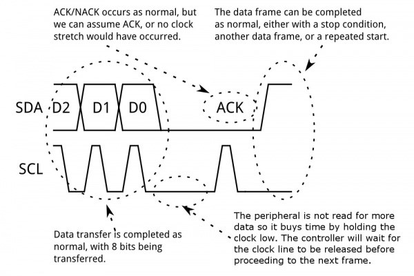
1.6 Concept of clock stretching.
Let say the master device started a transaction and sent address bits of a particular slave device followed by a Read bit of ‘1’.
The specific slave device needs to send an ACK bit, immediately followed by data.
But if the slave device needs some time to fetch and send data to master device, This can be because the data isn't ready yet
(for instance, the peripheral hasn't completed an analog-to-digital conversion yet) or because a previous operation hasn't yet completed
(say, an EEPROM which hasn't completed writing to non-volatile memory yet and needs to finish that before it can service other requests).
during this gap, the master device will think that the slave device is sending some data.
To prevent this, some peripheral devices will execute what is referred to as "clock stretching".
the slave device holds the SCL clock line low until it is ready to transfer data bits. By doing this, the slave device
signals the master device to wait for data bits until the clock line is released.
1.7 Advantages and Disadvantages of I2C.
Advantages
• Only uses two wires
• Supports multiple masters and multiple slaves
• ACK/NACK bit gives confirmation that each frame is transferred successfully
• Hardware is less complicated than with UARTs
• Well known and widely used protocol
Disadvantages
• Slower data transfer rate than SPI
• Capacitance on the bus lines needs to be considered strictly otherwise chances of making garbage of the data.
• The size of the data frame is limited to 8 bits
• Implementing I2C protocol on software level required rich knowledge for the instruction sets used to configure and use the device.
1.8 Comparing I2C to other serial communication protocol UART and SPI.
| UART (Universal Asynchronous Receiver Transmitter) | |
|---|---|
| Synchronizing Data Rate | Because UART is an asynchronous (no clock data is transmitted), device using them must agree ahead of time on a data rate. The two devices must also have clocks that are close to the same rate, and will remain so--excessive differences between clock rates on either end will cause garbled data. |
| Data bits | At least one start and stop bit is a part of each frame of data, meaning that 10 bits of transmission time are required for each 8 bits of data sent, which eats into the data rate, while with I2C for every 8 bits of data to be sent, one extra bit of meta data (the "ACK/NACK" bit, which we'll discuss later) must be transmitted. |
| Bus contention | UARTS are inherently suited to communications between two, and only two, devices. While it is possible to connect multiple devices to a single serial port, bus contention (where two devices attempt to drive the same line at the same time) is always an issue and must be dealt with carefully to prevent damage to the devices in question, usually through external hardware while The hardware required to implement I2C is more complex than SPI, but less than UARTs. It can be fairly trivially implemented in software. |
| Limited Baud Rates | most UART devices only support a certain set of fixed baud rates, and the highest of these is usually around 230400 bits per second. |
| SPI (Serial Peripherial Interface) | |
|---|---|
| Limited Controller | SPI only allows one controller on the bus, but it does support an arbitrary number of peripherals (subject only to the drive capability of the devices connected to the bus and the number of chip select pins available). |
| Full Duplex | SPI is good for high data rate full-duplex (simultaneous sending and receiving of data) connections, supporting clock rates upwards of 10MHz (and thus, 10 million bits per second) for some devices, and the speed scales nicely. |
| Implementation | The hardware at either end is usually a very simple shift register, allowing easy implementation in software while The hardware required to implement I2C is more complex than SPI, but less than UARTs. It can be fairly trivially implemented in software. |
| Number of Pins | The most obvious drawback of SPI is the number of pins required. Connecting a single controller to a single peripheral with an SPI bus requires four lines; each additional peripheral device requires one additional chip select I/O pin on the controller. The rapid proliferation of pin connections makes it undesirable in situations where lots of devices must be connected to one controller, while I2C can support a multi-controller system, allowing more than one controller to communicate with all peripheral devices on the bus (although the controller devices can't talk to each other over the bus and must take turns using the bus lines). |
| Complex routing signal | large number of connections for each device can make routing signals more difficult in tight PCB layout situations while I2C requires a mere two wires, but those two wires can support up to 1008 peripheral devices. |