In digital communication, the information we wish to send from the transmitter to the receiver are the bits. Bits of information can represent anything from ASCII characters in a Microsoft Word document, to numeric values that represent samples from an audio signal, to numeric values that represent the colors of pixels in a digital image. The information is carried in the bits that are transmitted, but we don’t actually transmit bits; we transmit waveforms that represent bits. These waveforms are commonly referred to as symbols.
Symbols are the physical means by which bits move from transmitter to receiver, and exactly how it is done depends on the communication medium being used. If we wish to send bits over a wire, we usually use voltage pulses. For example, a high pulse may represent a 1-bit and a low pulse (or no pulse) may represent a 0-bit (or vice versa). In this case, the voltage pulses are the symbols, and each pulse carries 1 bit of information. Using voltage pulses, the transmitter is sending one of two possible symbols (e.g. a high pulse or a low pulse), and the process of sending digital information with voltage pulses forms a baseband (low frequency) signal.
In almost all cases, the source information is impressed upon a carrier-wave (essentially a sinusoid of a certain frequency) by changing or modifying some characteristic of the sinusoidal wave. This process is called modulation. The original source signal (e.g., audio, voltage pulse train carrying digital information) is called the baseband signal.
Modulation has the effect of moving the baseband signal spectrum to be centered frequencies around the frequency of the carrier. The resulting modulated signal is considered a bandpass signal.
Usually, we are concerned about how fast the information is being transmitted, and this relates to symbol rate, which is the number of symbols per second being transmitted. Symbol rate is sometimes referred to as baud or baud rate, but they all mean the same thing. The figure below shows the relation between information (bits) and symbols (voltage pulses) for an example transmission.
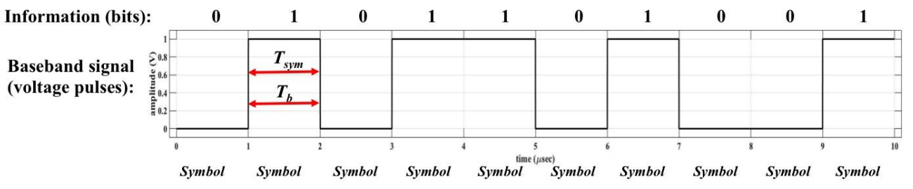
In the figure above, there are 10 total bits being transmitted, and they are carried in the 10 symbols shown. The time it takes to send one symbol is 1 µsec as shown. The symbol rate is the inverse of the time to transmit one symbol, and the bit rate is the inverse of the time to transmit one bit, i.e.,
In this example, since Tsym is 1 µsec, then Rsym=1/10-6 = 1 × 10⁶ symbols/sec. And, since each symbol carries 1 bit of information (that is, 1 bit/symbol), the bit rate is 1 × 106 bits/sec = 1 Mbps. In general, the symbol rate and bit rate are related by:
where N is the number of bits per symbol. In the figure above,
N = 1 bit/symbol,
leading to Rb=1 Mbps.
There is a relationship between the number of possible symbols that could be transmitted,
and the number of bits per symbol. The number of symbols available for the transmitter to transmit is variable M: that is,
there are possible M symbols, and the relationship is:
For the example in the previous figure, there are two possible symbols for the transmitter to transmit, and so N = log2(2) = 1 bit/symbol.
M-ary Encoding
M-ary is a term derived from the word binary(bin-ary). M simply represents a digit that corresponds to the number of conditions, levels,
or combinations possible for a given number of binary variables.
For example, a digital signal with four possible conditions (voltage levels, frequencies, phases, and so on) is an M-ary system where M = 4. If there are eight possible conditions, M = 8 and so forth. The number of bits necessary to produce a given number of conditions is expressed mathematically as
N = log2 M
where N = number of bits necessary
M = number of conditions, levels, or combinations possible with N bits
Equation can be simplified and rearranged to express the number of conditions possible with N bits as
2 N=M
For example, with one bit, only 21 = 2 conditions are possible. With two bits, 22 = 4 conditions are possible,
with three bits, 23 = 8
conditions are possible, and so on.
While it is possible to have any arbitrary value for M, most systems are constructed such that M = 2k .
In such a case, we can think of each one of the M symbols as containing
k bits.
For instance, if m1, m2, m3, and m4 are the symbols of a 4-ary system, we can associate the “dibit” 00 to m1, 01 to m2, 10 to m3, and 11 to m4.
Each one of the M symbols is usually represented by a unique signal that lasts for Ts seconds. The message signal is thus one of M discrete possibilities. We call Ts the symbol duration and 1 Ts as the symbol rate (expressed in units of baud). The bit rate (if M = 2k ) will be k Ts bits per second. Example. Each symbol occupies 1 µs, then the symbol rate is 1 M symbol/s or 1 Mbaud. If each symbol carries 4 bits (k = 4 or it is a M = 16-ary alphabet) and the bit rate is 4 Mbps.
In a manner similar to analog modulation, the message is mapped to the amplitude, frequency, phase (or a combination of these) of the carrier. Note however that there are a finite and discrete number of messages and each message has a corresponding amplitude, frequency or phase value.
Thus there are a discrete number of carriers with specific values of amplitude, frequency and phase values corresponding to a given alphabet. If the message is mapped only to the amplitude of the carrier, the modulation is called amplitude shift keying or ASK. If the message is mapped only to the frequency of the carrier, the modulation is called frequency shift keying or FSK. If the message is mapped only to the phase of the carrier, the modulation is called phase shift keying or PSK. A hybrid of amplitude and phase mapping is called quadrature amplitude modulation (QAM).
Binary Digital Modulation
Binary digital modulation refers to types of modulation where there are two symbols, and so each symbol carries 1 bit of information. we can use an information signal (message)
to modulate a carrier by varying its amplitude, frequency, or phase. So, how do we go about representing digital information (1s and 0s) with modulation? Just as we can vary amplitude,
frequency, and phase of a highfrequency carrier in accordance with an analog information (message) waveform, we can do the same with a digital waveform. Since bit values “shift”
between 0s and 1s, digital modulation techniques that vary the carrier’s amplitude, frequency, and phase are referred to as “shift keying.”.
Binary Modulation Schemes In the case of binary modulation schemes, the alphabet has two values “0” and “1.” In ASK, a “0” is mapped to one amplitude value and a “1” is mapped to another amplitude value. In FSK, a “0” is mapped to one frequency value and a “1” is mapped to another frequency value. In PSK, a “0” is mapped to one phase value and a “1” is mapped to another phase value. We call these modulation schemes BASK, BFSK and BPSK respectively to denote that the alphabet is binary. We discuss these schemes in more detail below.
If the information signal is digital and the amplitude of the carrier is varied proportional to the information signal, a digitally modulated signal called amplitude shift keying (ASK) is produced. If the frequency (f) is varied proportional to the information signal, frequency shift keying (FSK) is produced, and if the phase of the carrier (0) is varied proportional to the information signal, phase shift keying (PSK) is produced. If both the amplitude and the phase are varied proportional to the information signal, quadrature amplitude modulation (QAM) results. ASK, FSK, PSK, and QAM are all forms of digital modulation
INFORMATION CAPACITY, BITS, BIT RATE, BAUD, AND MARY ENCODING
Information Capacity, Bits, and Bit Rate
I α B x t
where I= information capacity (bits per second)
B = bandwidth (hertz)
t = transmission time (seconds)
It can be seen that information capacity is a linear function of bandwidth and transmission time and is directly proportional to both.
If either the bandwidth or the transmission time changes, a directly proportional change occurs in the information capacity.
The higher the signal-to-noise ratio, the better the performance and the higher the information capacity.
Mathematically stated, the Shannon limit_for information capacity is
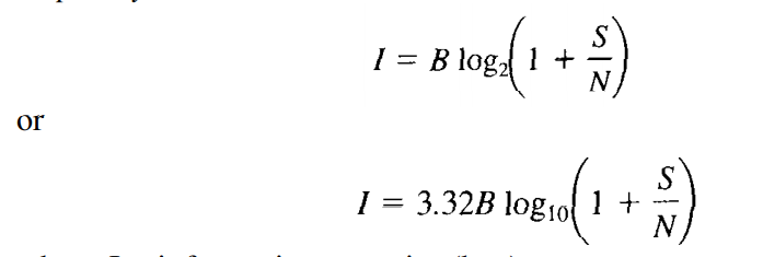
where I = information capacity (bps)
B = bandwidth (hertz)
S/N = signal-to-noise power ratio (unitless)
For a standard telephone circuit with a signal-to-noise power ratio of 1000 (30 dB) and a bandwidth of 2.7 kHz, the Shannon limit for information capacity is
I = (3.32)(2700) log10 (1 + 1000) = 26.9 kbps
Shannon's formula is often misunderstood. The results of the preceding example indicate that 26.9 kbps can be propagated through a 2.7-kHz communications channel. This may be true, but it cannot be done with a binary system. To achieve an information transmission rate of 26.9 kbps through a 2.7-kHz channel, each symbol transmitted must contain more than one bit.