A stack is an ordered collection of homogeneous data elements where the insertion and deletion operations take place at one end only. i.e stack operations obey the last-in, first-out principle, or LIFO. The insertion and 'deletion operations in the case of a stack are specially termed PUSH and POP, respectively, and the position of the stack where these operations are performed is known as the TOP of the stack. An element in a stack is termed an ITEM. The maximum number of elements that a stack can accommodate is termed SIZE. Figure shows a typical view of a stack data structure.
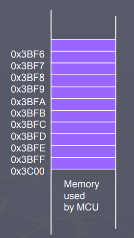
In the figure above, a portion of the computer memory is mapped out as the stack. Data are continuously added to the stack using their address as shown. And the last data to be written to the stack has to be first data to be read. Last-in first-out data structure (LIFO)
The Stack Pointer (SP) register is used to indicate the location of the last item put onto the stack.
SP points to location last item placed in block
SP decreases when you put an item on the stack
SP increases when you pull the item from the stack
When you PUT something ONTO the stack (PUSH onto the stack), the SP is decremented before the item is placed on the stack.
When you take something OFF of the stack (PULL from the stack), the SP is incremented after the item is pulled from the stack.
Before you can use a stack you have to initialize the SP to point to one value higher than the highest memory location in the stack.
Applications of Stacks
UNDO and REDO buttons
We always use these two buttons whenever we navigate through an on our computer. Actions you take while using an application are continuously stored within the stack memory.
And when there is a need to undo a particular action whenever the first or last step you take, you have to use the undo button.
This button basically pops out or reads or repeats each of your previous steps starting from your last step to the particular step you would like to undo. And when you have to redo a particular action, the last action you cleared pops out from a different stack memory till the particular action you would like to redo.
Stack Calculator
I would be explaining a stack calculator which I designed using Verilog in this tutorial. I used two stack memory one for numbers and another for arithmetic or logic operation.
Here the data are continuously added or pushed into the memory while they are being compared to select the operation based on preference , and when a particular operation is
selected it is popped out of the stack memory , then calculated at the ALU and then pushed back into the register.
Back and Forward Buttons in a Web Browser
Each time the user moves to a new web page, the current web page is stored on a stack. Pressing the back button causes the topmost element of this stack to be popped, and the
associated web page is displayed.
However, that explanation really provided only half the story. To allow the user to move both forward and backward two stacks are employed. When the user presses the back button, the link to the current web page is stored on a separate stack for the forward button. As the user moved backward through previous pages, the link to each page is moved in turn from the back to the forward stack.
When the user pushes the forward button, the action is the reverse of the back button. Now the item from the forward stack is popped, and becomes the current web page. The previous web page is pushed on the back stack.
Stack operations
PUSH Operation
The process of putting a new data element onto stack is known as PUSH Operation. Push operation involves series of steps
Step 1 − Check if stack is full.
Step 2 − If stack is full, produce error and exit.
Step 3 − If stack is not full, increment top to point next empty space.
Step 4 − Add data element to the stack location, where top is pointing.
Step 5 − return success.
Pop Operation
Accessing the content while removing it from stack, is known as pop operation. In array implementation of pop operation, data element is not actually removed,
instead top is decremented to a lower position in stack to point to next value.
But in linked-list implementation, pop actually removes data element and deallocates memory space. A POP operation may involve the following steps –
Step 1 − Check if stack is empty.
Step 2 − If stack is empty, produce error and exit.
Step 3 − If stack is not empty, access the data element at which top is pointing.
Step 4 − Decrease the value of top by 1.
Step 5 − return success.
top()/peek():
Return a reference to the top element on the stack, without removing it; an error occurs if the stack is empty .
isFull − check if stack is full.
size(): Return the number of elements in the stack
isEmpty(): Return true if the stack is empty and false otherwise
The stack calculator design computes complex algebra, including mix of arithmetic operators and logical operators. E.g. 2 + 2 * 5 & 12 – 32 / 8 | 9 ^ 5, with the exception of a bracket.
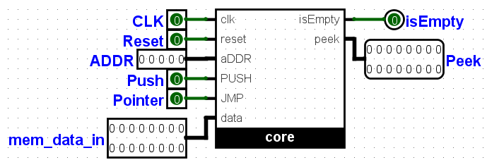
The figure above is the logism circuit, it takes as an input clock
And reset, which are used for synchronizing the circuit. mem_data_in which is the data to be operated on, push button which push the input in.
Since the stack goes in through one end and comes out through the same end. The ADDR, is used to jump to a particular point in memory incase where input and output from
one end is not necessary, with the pointer button acting as the jump button.
The outputs are isEmpty (which detects that the stack has completely
solved the complex arithmetic and now empty) and Peek (This is the top of the stack, at ADDR 0, which is what is left after solving the maths).
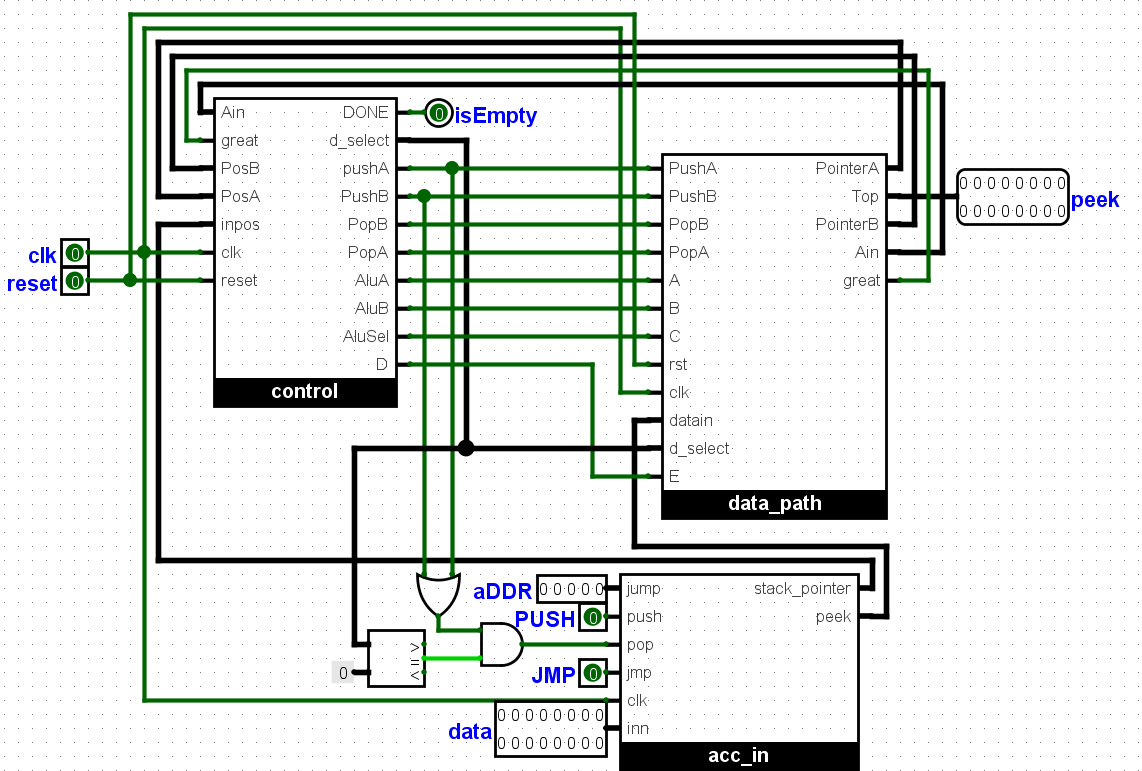
A look into the circuit reveals the sub circuits above, they are three, 1. the control sub circuit which consists of the control data, this reads the operators and tells the stack when to push or pop. And where to push the popped data, whether to the ALU or to another stack.
2. The acc_in sub circuit, this is used
input the data, all the inputs including numbers, logical and arithmetic operators are pushed in here, using the data and push, input and button
respectively, The jmp button and ADDR input are used to jump to particular address in memory. The pop, is directly connected to the
control sub circuit, which decides when to pop data, the outputs peek which represents the top , carries the popped data to another sub circuit, and the
stack_pointer, is the current address which is fed to the control, to detect when the inputs are finished or isEmpty.
3. Datapath, This sub circuit contains the actual stack memory, and ALU . All data are stored here, and from here then pushed or popped, to and from the ALU. When data are popped from the stack memory, they are pushed to the ALU where it is being calculated and later transferred back to the stack.
Two stack exists here, One stores the Numbers, another stores the arithmetic and logic operators.
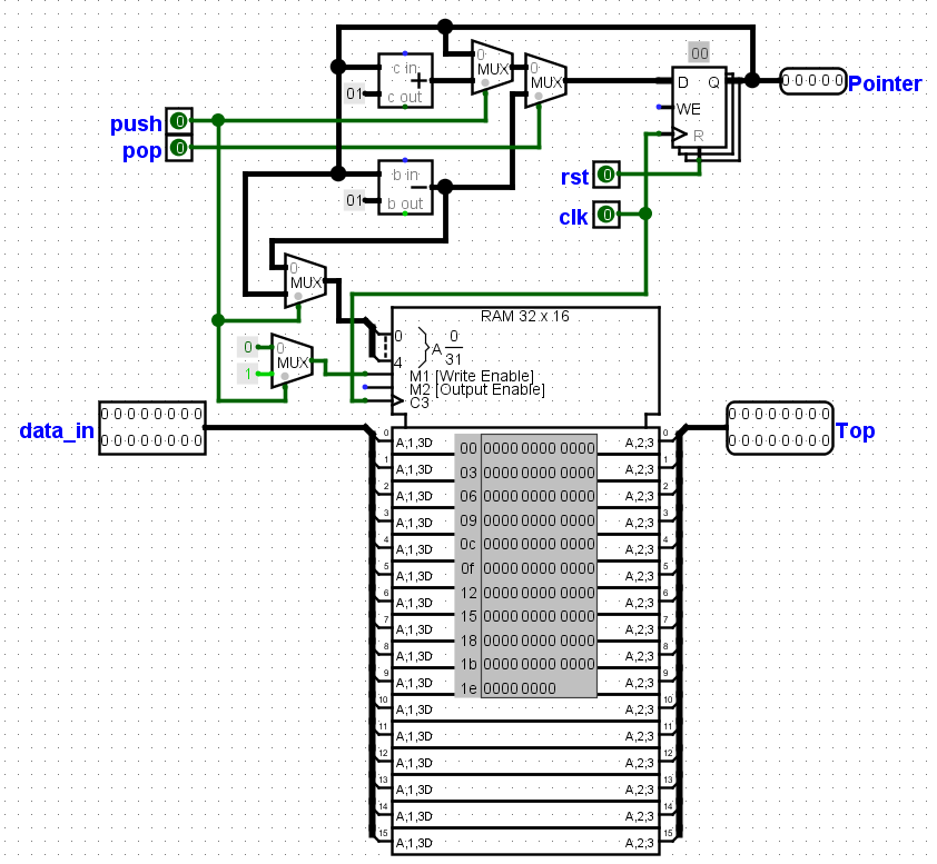
The typical stack circuit is shown above, it has the stack memory and stack register. The stack register contains the stack pointer which points to the address in memory.
The Push and Pop, buttons are used increment and decrement the stack register. And this decides the address to be written or read from. The Two
multiplexers towards the memory are used decrement the stack pointer more during a read or pop operation, because the pointer points to the next address to be
read and not the current address. The next multiplexer makes sure data is not written to the ram during a read or pop operation.
The YouTube video series below will explain on the working of the stack calculator, and the Verilog scripts can be found below.
The algorithm
Take the maths example below:
22 x 2 + 10 / 2 – 5 x 4 = 29
Step 1:
Each of the characters are pushed into the acc_in subcircuit starting from the last character i.e 4, all in binary, the MSB of all figures is given 0,
while the operators is 1. The first character before the 4, is 1000 0000 0000 0000. This operator returns the final output back to the stack. And asserts finish.
The values are given in binary, values for the operators are from their position in the ALU.
Step 2:
Step3:
Step4:
Step5:
Step6:
Step7:
Step8:
Step9:
Step10:
Return answer (since stack pointers of stackA, stackB and input are all at one or zero)
29 is returned as the final answer.
From above, we can see that the algorithm is (pop stackB twice, compare the signs, pop stackA twice , push stackA and stackB once, if the sign with higher priority appears first.) or (pop stackB twice, compare the sign, push stackB twice, if the sign with lesser priority appears first.)