Orthogonal frequency-division multiplexing (OFDM) is a method of digital modulation in which a signal is split into several narrowband channels at different frequencies.
The traditional format for sending data over a radio channel is to send it serially, one bit after another. This relies on a single channel and any interference on that single frequency can disrupt the whole transmission. OFDM adopts a different approach. The data is transmitted in parallel across the various carriers within the overall OFDM signal. Being split into a number of parallel "substreams" the overall data rate is that of the original stream, but that of each of the substreams is much lower, and the symbols are spaced further apart in time. This reduces interference among symbols and makes it easier to receive each symbol accurately while maintaining the same throughput.
The lower data rate in each stream means that the interference from reflections is much less critical. This is achieved by adding a guard band time or guard interval into the system. This ensures that the data is only sampled when the signal is stable and no new delayed signals arrive that would alter the timing and phase of the signal. This can be achieved far more effectively within a low data rate substream.
Modulation is the integration of a bassband signal with a carrier signal using the changes in frequency, phase or amplitude (or a combination of them) while Multiplexing deals with allocation of users in a given bandwidth (i.e. it deals with allocation of available resource).
OFDMis a combination of both modulation and multiplexing. In this technique, the given resource (bandwidth) is shared among individual modulated data sources.
Normal modulation techniques (like AM, PM, FM, BPSK, QPSK, etc.., ) are single carrier modulation techniques, in which the incoming information is modulated over a single carrier. OFDM is a multicarrier modulation technique, which employs several carriers, within the allocated bandwidth, to convey the information from source to destination. Each carrier may employ one of the several available digital modulation techniques (BPSK, QPSK, QAM etc..,). OFDM is a special case of FDM ( Frequency Division Multiplexing). In FDM, the given bandwidth is subdivided among a set of carriers. There is no relationship between the carrier frequencies in FDM.For example, consider that the given bandwidth has to be divided among 5 carriers (say a,b,c,d,e). There is no relationship between the subcarriers ; a,b,c,d and e can be anything within the given bandwidth. If the carriers are harmonics, say (b=2a,c=3a,d=4a,d=5a , integral multiple of fundamental component a ) then they become orthogonal. This is a special case of FDM, which is called OFDM (as implied by the word – ‘orthogonal’ in OFDM)
Two conditions must be met for subcarrier orthogonality:
1.Each subcarrier has exactly an integer number of cycles in the Discrete Fourier Transform interval.
2.The number of cycles between adjacent subcarriersdiffers by exactly one cycle
OFDM transmitter Divides the information into several parallel sub-streams✓Sends each sub-stream on a different frequency (sub-carrier)‣If the total data rate stays the same, then -The data rate on each sub-carrier is less than before, so the symbol duration is longer‣This reduces the amount of ISI, and reduces the error rate. In time domain, OFDM breaks one serial fast bit stream into many parallel slow bit streams. Then, these parallel slow bit streams are multiplied with orthogonal sinusoids, where orthogonality between two sinusoids is defined with a summation over a certain time interval as
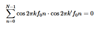
when k≠k'.This process is illustrated in details below with the help of an example:
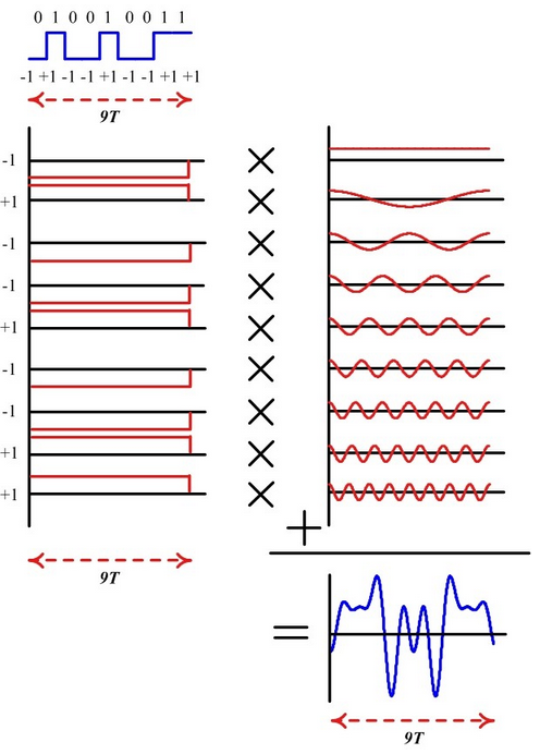
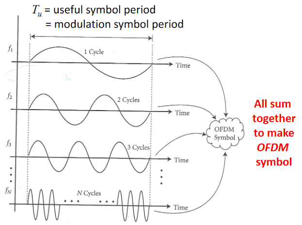
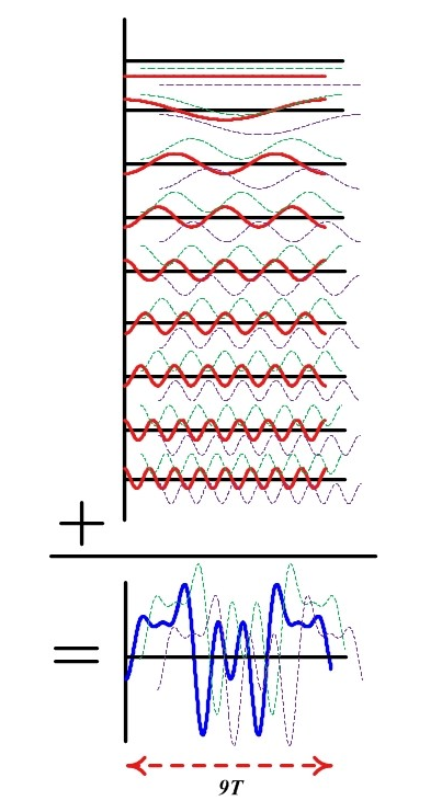
For a bit stream in the example above traces the following steps: I. Assume that the bit duration is T and there are 9 bits to be sent. In a high speed communication system, it will take 9T seconds to transmit all the bits. So we break them down to 9 parallel bit streams each with a duration of 9T seconds.
II. Assume a fundamental frequency of f0=1/9T with 9 samples within this duration (that will be one complete period). Then, this sinusoid will be orthogonal to 8 other sinusoids with frequencies 0f0, 2f0, 3f0, ⋯, 8f0 . This set of 9 sinusoids is shown above, We will call them subcarriers.
III. Next, we multiply each such sinusoid with +1 or −1 (depending on the bit) to scale their amplitude accordingly.
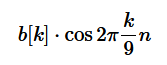
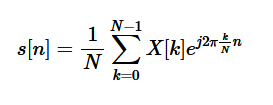
iV. Finally, all these amplitude scaled sinusoids are added together to generate the desired signal. Notice that this composite signal has a duration of 9T seconds (same duration as the original bit stream) but contains the information from all 9 bits. For a bit stream say b[k] mapped to a non-binary modulation scheme X[k] (having I and Q components) and N sinusoids (instead of 9), this sequence of steps can be carried out using the inverse Discrete Fourier Transform (iDFT) defined as
For each such individual signal, the multi-path components arrive in not too distant future (just like a low rate stream above). The multi-path components for individually modulated subcarriers as well as for the composite signal, First and second path respectively shown up and down for clarity below.
Hence, the equalizer design is easy having less spread paths and consequently less interference with future symbols, provided that we find a way to separate the subcarriers at the Rx. Separating these bits at the Rx is easy: we can correlate (multiply sample by sample and sum) the composite signal with just one subcarrier, say with frequency 6f0 . Utilizing their orthogonality property, contribution from all other 8 subcarriers will cancel out to zero, while the contribution from the subcarrier with that frequency 6f0 will pop out, scaled in amplitude by our modulation signal. The same procedure can be repeated for all other subcarriers. Essentially, this is an operation of Discrete Fourier Transform (DFT) as
The mathematical description for the OFDM signal is given as follows: The low-pass equivalent OFDM signal is expressed as
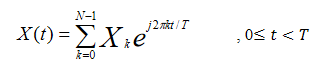
Here Xk are data symbols which is sequence of complex numbers representing BPSK, QPSK or QAM baseband symbol, N is number of subcarriers and T is OFDM symbol line. The subcarrier spacing 1/T makes them orthogonal over each symbol period. Sequence of OFDM symbols is given as follows:
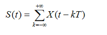
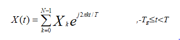
To avoid ISI, a guard interval of length Tg is inserted before OFDM block. During this interval, a cyclic prefix is transmitted. The signal with cyclic prefix is thus given as,
In summary, remember that time and frequency have inverse relationship. A signal wide in time domain has a narrow frequency span and vice versa. Although this relationship can be derived, we can just look into the Fourier transform of a rectangular signal: a sinc signal. The wider the rectangle, the earlier the sinc's first zero-crossing is. Therefore, a low rate signal being wide in time domain has a narrow spectral representation. On the other hand, a fast rate signal exhibiting rapid changes in time has a wide spectrum.
• In time domain, OFDM converts one serial fast bit stream into many parallel slow bit streams.
• In frequency domain, OFDM segments one wide spectrum into many narrow spectra.
The FFT Block
To begin the OFDM signal creation process, the input data bit stream is encoded with convolutional coding and Interleaving.
Each data stream is divided into groups of "n" bits (1 bit -BPSK, 2 bits -QPSK, 4 bits -16QAM, or 6 bits -64QAM)
and converted into complex numbers (I+jQ) representing the mapped constellation point. Note that the bit-rate will be different depending on the modulation format,
a 64-QAM constellation (6 bits at a time) can have a bit rate of 54 Mbps while a QPSK constellation (2 bits at time) may only be 12 Mbps.
Then 52 bins of the IFFT block are loaded. 48 bins contain the constellation points which are mapped into frequency offset indexes ranging from -26 to +26, skipping the 4 Pilot and zero bins. There are 4 Pilot subcarriers inserted into frequency offset index locations -21, -7, +7, and +21. The zero bin is the Null or DC subcarrier and is not used; it contains a 0 value (0+j0).The Fast Fourier Transform (FFT) is a computationally efficient implementation of DFT. Inverse Fast Fourier Transform (IFFT) and FFT are main modulation and demodulation techniques used in OFDM.
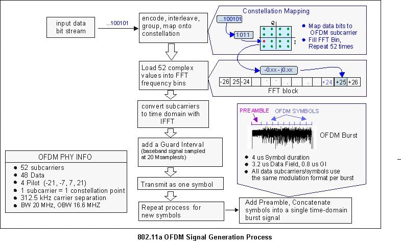
When the IFFT block is completely loaded, the Inverse FFT is computed, giving a set of complex time-domain samples representing the combined OFDM subcarrier waveform. The samples are clocked out at 20 Msps to create a 3.2 us (20Msps/64) duration OFDM waveform. To complete the OFDM symbol, a 0.8 us duration Guard Interval (GI) is then added to the beginning of the OFDM waveform. This produces a "single" OFDM symbol with a time duration of 4 us in length, (3.2 us + 0.8 us). The process is repeated to create additional OFDM symbols for the remaining input data bits.
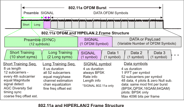
To complete the OFDM frame structure, the single OFDM symbols are concatenated together and then appended to a 16 us Preamble (used for synchronization) and a 4 us SIGNAL symbol (provides Rate and Length information). This completes the OFDM frame and is ready to be transmitted as an OFDM Burst.
Now, Things to consider when sending an example data bits using OFDM : D = {d0,d1,d2,…). The first thing that should be considered in designing the OFDM transmitter is the number of subcarriers required to send the given data. An OFDM subcarriers signal is the sum of one or more OFDM symbols each comprised of N orthogonal subcarriers ( 52 subcarriers; 48 are data subcarriers and 4 are pilot subcarriers) with Each subcarriers centered at frequencies that are orthogonal to each other (usually multiples of frequencies) and baseband data on each subcarrier. This composite baseband signal is used to modulate a main RF carrier. Pilot subcarriers are always modulated using BPSK and a known magnitude and phase. Each OFDM subcarrier carries a single modulated data symbol, or "constellation point", along with its magnitude and phase information . This means that the magnitude and phase will vary for each subcarrier and OFDM symbol in the transmitted burst.
The second design parameter could be the modulation format that we wish to use. An OFDM signal can be constructed using anyone of the following digital modulation techniques namely BPSK, QPSK, QAM etc.., The data (D) has to be first converted from serial stream into parallel stream depending on the number of sub-carriers (N). Since we assumed that there are N subcarriers allowed for the OFDM transmission, we name the subcarriers from 0 to N-1. Now, the Serial to Parallel converter takes the serial stream of input bits and outputs N parallel streams (indexed from 0 to N-1). These parallel streams are individually converted into the required digital modulation format (BPSK, QPSK, QAM etc..,). Lets call this output S0,S1,..SN.
The conversion of parallel data (D) into the digitally modulated data (S) is usually achieved by a constellation mapper, which is essentially a look up table (LUT). Once the data bits are converted to required modulation format, they need to be superimposed on the required orthogonal subcarriers for transmission. This is achieved by a series of N parallel sinusoidal oscillators tuned to N orthogonal frequencies (f0,f1,…fN-1). Finally, the resultant output from the N parallel arms are summed up together to produce the OFDM signal.
The following figure illustrates the basic concept of OFDM transmission (note: In order to give a simple explanation to illustrate the underlying concept, the usual IFFT/FFT blocks that are used in actual OFDM system, are not used in the block diagram) .Note also that All data subcarriers use the same modulation format within a given burst.However, the modulation format can vary from burst to burst.
OFDM Frame Structure
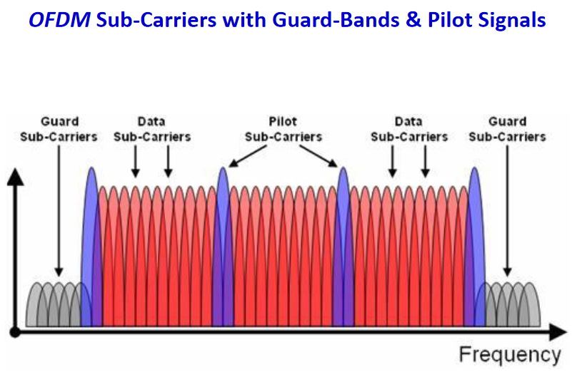
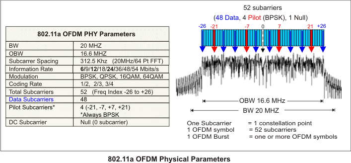
Example above: OFDMSubcarriers in 802.11a/g Wi-FiEach 20 MHz channel, whether it's 802.11a/g/n/ac, is composed of 64 sub-carriers spaced 312.5 KHzapart. This spacing is chosen because 64-point FFT sampling was used. 802.11a/g use 48 subcarriers for data, 4 for pilot, and 12 as null subcarriers. 802.11n/ac use 52 subcarriers for data, 4 for pilot, and 8 as null.
The basic frame structure of an 802.11a OFDM Frame burst contains a preamble field followed by a SIGNAL field and multiple data fields. At the start of the burst, a preamble is transmitted at a well-known magnitude and phase. The preamble is used for synchronization and channel equalization. The SIGNAL field (not used in HIPERLAN 2 signals) is transmitted using BPSK, and contains the length, modulation type, and data rate information. Then multiple OFDM symbols containing the input data bits are appended to complete the burst.
The following table lists the timing parameters associated with the 802.11a signal:
| Parameter | Value |
|---|---|
| Total subcarriers NST | 52 |
| Data subcarriers NSD | 48 |
| Pilot subcarriers NSP | 4 (subcarriers -21, 7, 7, 21) |
| Subcarrier Frequency Spacing FSP | 312.5 KHz (20MHz/64) |
| Symbol Interval Time TSYM | 4 us (TGI +TFFT) |
| Data Interval Time TDATA | 3.2 us (1/FSP) |
| Guard Interval (GI) Time TGI | 0.8 us (TFFT/4) |
| IFFT/FFT Period TFFT | 3.2 us (1/FSP) |
| SIGNAL Symbol TIme TSIGNAL | 4 us (TGI +TFFT |
| Preamble TPREAMBLE | 16 us (TSHORT +TLONG) |
| Short Training Sequence TSHORT | 8 us (10xTFFT/4) |
| Long Training Sequence TLONG | 8 us (TGI2 + 2xTFFT) |
| Training symbol GI TGI2 | 1.6 us (TFFT/2) |
| FFT sample size | 64 point |
Cyclic prefix
One limitation of OFDM in many applications is that it is very sensitive to frequency errors caused by frequency differences between the local oscillators in the transmitter
and the receiver.
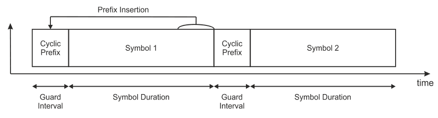
One way to prevent this error also known as ISI(Inter symbol Interference) is to create a cyclically extended guard interval,
where each OFDM symbol is preceded by a periodic extension of the signal itself. i.e The last section of a symbol is used as a preFIx in the front of the symbol.
When the guard interval is longer than the channel impulse response or multipath delay, the ISI can be eliminated.
Cyclic prefix insertion is commonly used in orthogonal frequency division multiplexing (OFDM) systems as a way to mitigate the effects of intersymbol-interference (ISI). It copies the end section of an inverse fast Fourier transform (IFFT) packet to the beginning of an OFDM symbol. Usually the length of the cyclic prefix is longer than the length of the dispersive channel to completely remove ISI.
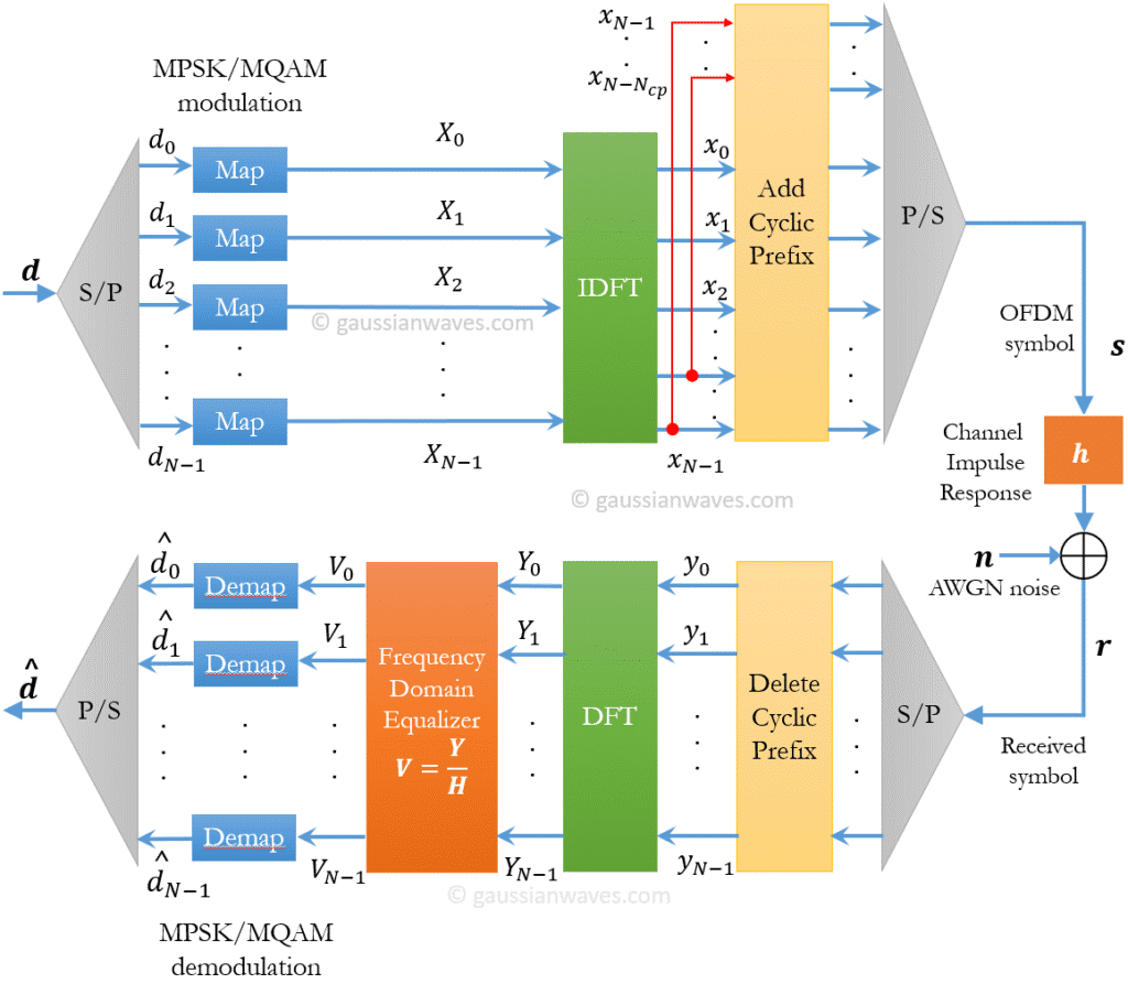
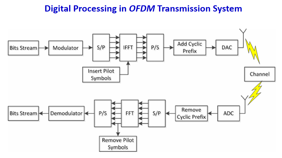
OFDM modulation therefore mostly revolves around cyclic prefix: OFDM modulation includes IFFT operation and cyclic prefix insertion; OFDM demodulation includes cyclic prefix removal and FFT operation.
Modern communications systems feature highly dynamic scalability, which often requires changing system parameters on-the-fly based on channel conditions and user quality of service (QoS) requirements. This design example demonstrates cyclic prefix insertion and removal for a reconfigurable OFDM system using the FFT Intel® FPGA intellectual property (IP) core. It supports run-time reconfiguration of FFT size and cyclic prefix size. Consider a non-ideal channel h(t)≠δ(t), that causes delay dispersion. Delay dispersion manifests itself as Inter Symbol Interference (ISI) on each subcarrier channel due to pulse overlapping. It will also cause ICC (Inter Carrier Interference ) due to the non-orthogonality of the received signal. Adding cyclic prefix to each OFDM symbol mitigates the problems of ISI and ICC by removing them altogether.
Lets say, without cyclic prefix we transmit the following N values (N=Nfft=length of FFT/IFFT) for a single OFDM symbol.
$$ X_0,X_1,X_2,…,X_{N-1} $$
Lets consider a cyclic prefix of length Ncp, ( where Ncp
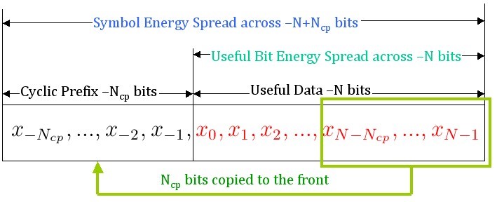
If T is the duration of the an OFDM symbol in secs, due to the addition of cyclic prefix of length Ncp , the total duration of an OFDM symbol becomes T+Tcp, where Tcp= Ncp*T/N. Therefore, the number of samples allocated for cyclic prefix can be calculated as Ncp = Tcp * N/T, where N is the FFT/IFFT length, T is the IFFT/FFT period and Tcp is the duration of cyclic prefix.
Transmitter
✓After the addition stage towards the end
The data represent the in-phase and quadrature components of the transmitted signal, as a function of time
The mixing and addition steps have simply converted the data from a function of frequency to a function of time. This conversion is called the inverse discrete Fourier transform(DFT). The Fourier transform converts data from the time domain to the frequency domain, so the transmitter requires an inverse transform, which carries out the reverse process. In turn, the discrete Fourier transform can be implemented extremely quickly using fast Fourier transform (FFT) .This limits the computational load on the transmitter and receiver, and allows the two devices to be implemented in a computationally efficient way.
However, there is one important restriction which is that for the FFT to work efficiently, the number of data points should be either an exact power of two or a product of small prime numbers alone.
In OFDM we have N carriers, N can be anywhere from 16 to 1024 in present technology and depends on the environment in which the system will be used. Let’s examine the following bit sequence we wish to transmit and show the development of the ODFM signal using 4 sub-carriers.
The signal has a symbol rate of 1 and sampling frequency is 1 sample per symbol, so each transition is a bit.
First few bits are 1, 1, -1, -1, 1, 1, 1, -1, 1, -1, -1, -1, -1, 1, -1, -1, -1, 1,... .
Let’s now write these bits in rows of fours, since this demonstration will use only four sub-carriers. We have effectively done a serial to parallel conversion. Table I – Serial to parallel conversion of data bits.
       c1  c2  c3  c4
       1   1   -1  -1
       1   1    1  -1
       1  -1   -1  -1
      -1   1   -1  -1
      -1   1    1  -1
      -1  -1    1   1
Each column represents the bits that will be carried by one sub-carrier. Let’s start with the first carrier, c1. What should be its frequency? From the Nyquist sampling Theorem, we know that smallest frequency that can convey information has to be twice the information rate. In this case, the information rate per carrier will be 1/4 or 1 symbol per second total for all 4 carriers. So the smallest frequency that can carry a bit rate of 1/4 is 1/2 Hz. But we picked 1 Hz for convenience. Had I picked 1/2 Hz as my starting frequency, then my harmonics would have been 1, 3/2 and 2 Hz. I could have chosen 7/8 Hz to start with and in which the harmonics would be 7/4, 7/2, 21/2 Hz.
We pick BPSK as our modulation scheme for this example. (For QPSK, just imagine the same thing going on in the Q channel, and then double the bit rate while keeping the symbol rate the same.) Note that I can pick any other modulation method, QPSK, 8PSK 32-QAM or whatever. No limit here on what modulation to use. I can even use TCM which provides coding in addition to modulation.
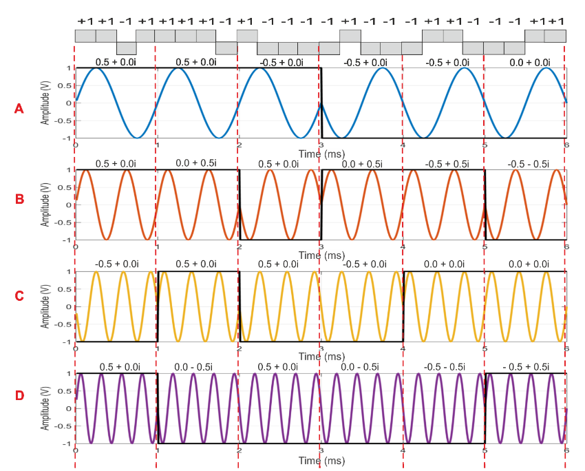
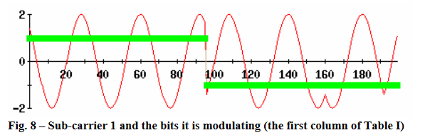
Carrier 1 - We need to transmit 1, 1, 1 -1, -1, -1 which I show below superimposed on the BPSK carrier of frequency 1 Hz. First three bits are 1 and last three -1. If I had shown the Q channel of this carrier (which would be a cosine) then this would be a QPSK modulation.
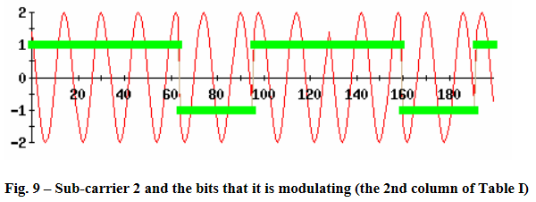
Carrier 2- The next carrier is of frequency 2 Hz. It is the next orthogonal/harmonic to frequency of the first carrier of 1 Hz. Now take the bits in the second column, marked c2, 1, 1, -1, 1, 1, -1and modulate this carrier with these bits as shown in Fig below
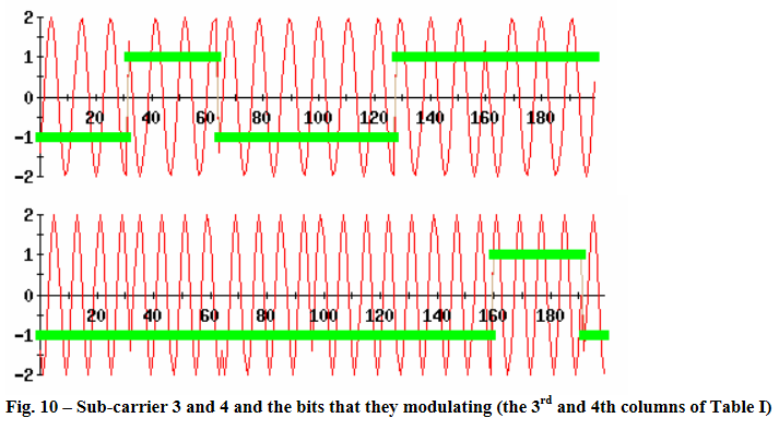
Carrier 3 – Carrier 3 frequency is equal to 3 Hz and fourth carrier has a frequency of 4 Hz. The third carrier is modulated with -1, 1, 1, -1, -1, 1 and the fourth with -1, -1, -1, -1, -1, -1, 1 from Table above
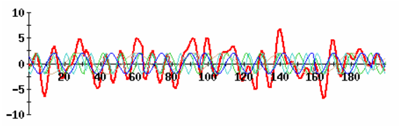
Now add all four of these modulated carriers to create the OFDM signal, often produced by a block called the IFFT.
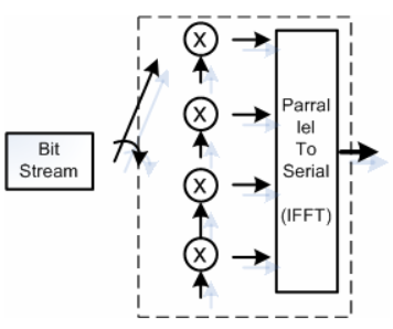
Functional diagram of an OFDM signal creation is shown below. The outlined part is often called an IFFT block.