Designed in 1984 by researchers at Stanford University and Short for Microprocessor without Interlocked Pipelined Stages, MIPS is a microprocessor architecture using the RISC instruction set (RISC processors typically support fewer and much simpler instructions), Compared with their CISC (Complex Instruction Set Computer) counterparts (such as the Intel Pentium processors), It can also stand for millions of instructions per second, here it is the approximate number of instructions a CPU can execute in one second. For example, the Intel 80386 computer processor was capable of performing more than five million instructions every second, or 5 MIPS.
The premise is, however, that a RISC processor can be made much faster than a CISC processor because of its simpler design. These days, it is generally accepted that RISC processors are more efficient than CISC processors; and even the only popular CISC processor that is still around (Intel Pentium) internally translates the CISC instructions into RISC instructions before they are executed.
RISC processors typically have a load-store architecture. This means there are two instructions for accessing memory: a load (l) instruction to load data from memory and a store (s) instruction to write data to memory. It also means that none of the other instructions can access memory directly. So, an instruction like "add this byte from memory to register 1" from a CISC instruction set would need two instructions in a load-store architecture: "load this byte from memory into register 2" and "add register 2 to register 1".
However, there are significant differences between the RISC approach and the approach used in MIPS:
1. The RISC architecture is simple both in the instruction set and the hardware needed to implement that instruction set. Although the MIPS instruction set has a simple hardware implementation (i.e. it requires a minimal amount of hardware control), the user level instruction set is not as straightforward, and the simplicity of the user level instruction set is secondary to the performance goals.
2. The thrust of the RISC design is towards efficient implementation of a straightforward instruction set. In the M1PS design, high performance from the hardware engine is a primary goal, and the microengine is presented to the end user with a minimal amount of interpretation. This makes most of the microcngine's parallelism available at the instruction set level.
3. The RISC project relies on a straightforward instruction set and straightforward compiler technology. MIPS will require more sophisticated compiler technology and will gain significant performance benefits from that technology. The compiler technology allows a microcode-level instruction set to appear like a normal instruction set to both code generators and assembly language programmers.
PIPELINING :In computers, a pipeline is the continuous and somewhat overlapped movement of instruction to the processor or in the arithmetic steps taken by the processor to perform an instruction. Pipelining is the use of a pipeline. Without a pipeline, a computer processor gets the first instruction from memory, performs the operation it calls for, and then goes to get the next instruction from memory, and so forth. While fetching (getting) the instruction, the arithmetic part of the processor is idle. It must wait until it gets the next instruction. With pipelining, the computer architecture allows the next instructions to be fetched while the processor is performing arithmetic operations, holding them in a buffer close to the processor until each instruction operation can be performed. The staging of instruction fetching is continuous. The result is an increase in the number of instructions that can be performed during a given time period.
Pipelining is sometimes compared to a manufacturing assembly line in which different parts of a product are being assembled at the same time although ultimately there may be some parts that have to be assembled before others are. Even if there is some sequential dependency, the overall process can take advantage of those operations that can proceed concurrently.
Computer processor pipelining is sometimes divided into an instruction pipeline and an arithmetic pipeline. The instruction pipeline represents the stages in which an instruction is moved through the processor, including its being fetched, perhaps buffered, and then executed. The arithmetic pipeline represents the parts of an arithmetic operation that can be broken down and overlapped as they are performed.
Pipelines and pipelining also apply to computer memory controllers and moving data through various memory staging places.
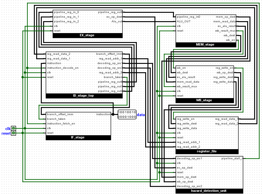
Design of the MIPS Processor
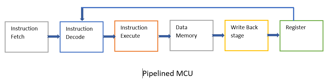
We will study the design of a simple version of MIPS, it is a 16bit pipelined MIPS. We will discuss each of the six stages with the hazard detection unit. The stages include:
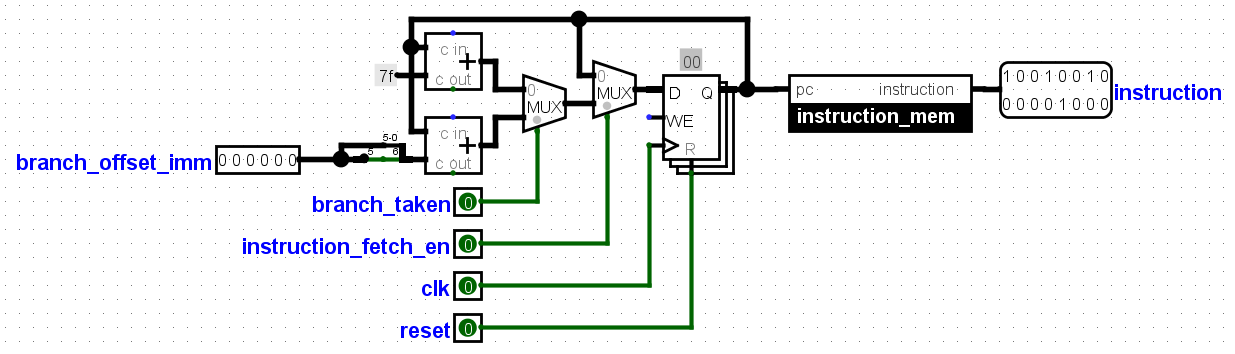
1. Instruction Fetch : This stage, Instructions are fetched from the instruction memory, Using the program counter as the memory address. The program counter is a
count-down timer which fetches data from the memory. The branch_taken signal if enabled jumps the program counter to an address given in the
branch_offset_imm signal. The instruction memory is a rom which can be for an example CD, Floppy disk e.t.c.
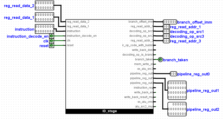
2. Instruction Decode: At this stage the instruction from the fetch stage and data from the registers are fed here to be decoded. The branch_jump signal is also
generated here. The pipelined_reg signal consisting of the ALU data, ALU_command, mem_write_en and data_memory data are also generated here.
The pipelined_reg signal is the largest signal consisting of 57bits and would be moved through different stages where some of the signals will be utilized
and new signals added. More explanation is given in the video below.
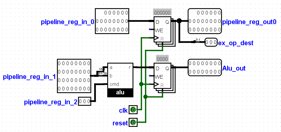
3. Instruction Execute:Here, part of the pipelined_reg signal will be used. It consists of 35bits out of the 57bits. The remaning 22bits would be
moved to the next stage. The 35bits consists of 3bits for the ALU command, and two 16bits for the two ALU inputs.
The alu is found here, it consists of 16 instructions,
the alu_command signal controls the multiplexer which selects the instruction. The output of the alu, alu_out is fed to the next stage also.
4. Data Memory :Another memory can be found here, the data memory. This is a ram that can be read or written to. The alu_out signal serves as
the address to this memory, while 16bit data from the pipelined_reg signal is used as the data to be written and another single bit is used as the write
enable bit for the data memory. The alu_out signal and the data from the data memory are the major outputs from this stage.
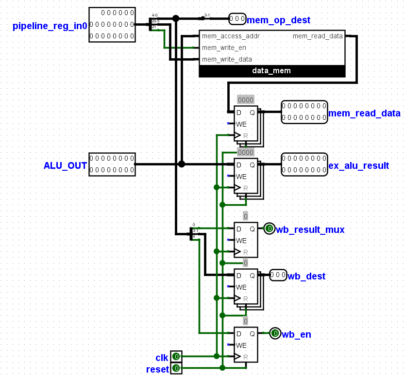
5. Write Back stage :The wb_result_mux signal which was generated from the previous stage selects between the data from the data memory and the
alu_output signal.The selected signal is moved to the next stage and the other , dropped.
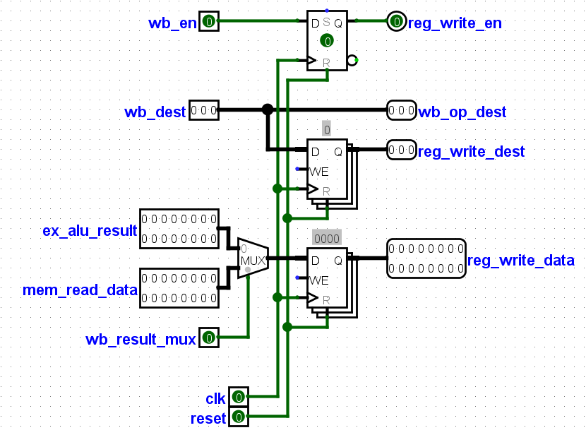
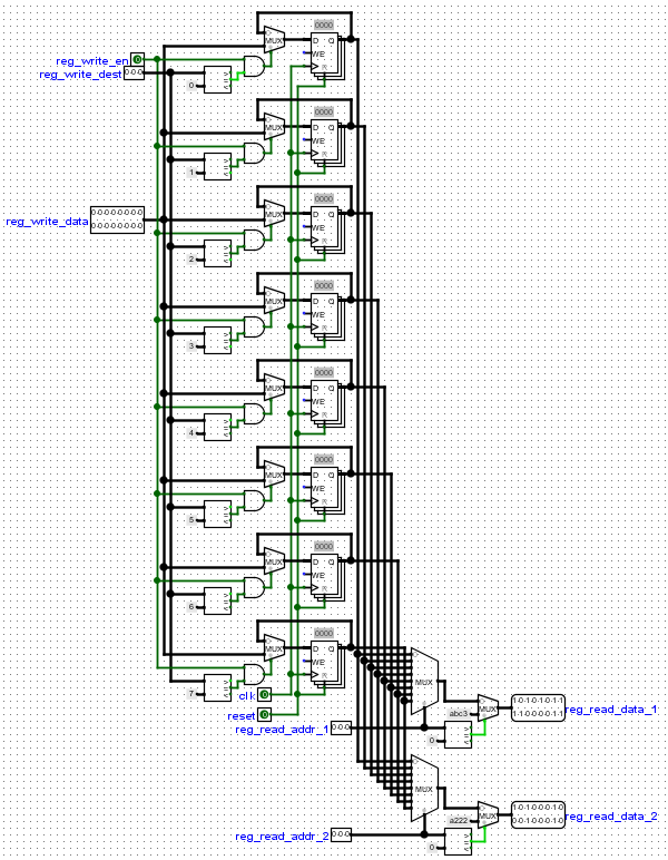
6. Registers:The selected data from the previous stage is used as the input data to the register.The are sixteen 16bit registers that can be written to, the
reg_write_en signal enable the registers to be written to, while the reg_write_dest selects the register to be written to, all signals comes
from the previous stage.
While the Write back stage is able to write to this register, The Instruction decode stage reads from these registers. Two signals representing addresses of two registers which the Instruction decoder wants to read are used.
In conclusion, Pipelining separates data processing in to stages or steps with each data processed one stage after another. Pipelining is faster because at every point in time a data is being processed on all the stages.